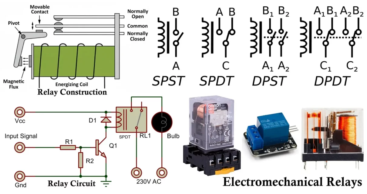
Electromechanical relay (EMR) is one of the oldest and still most widely used switching devices in electronics and electrical engineering. A relay is an electromechanical switching component that uses an electromagnet to mechanically operate a set of contacts. In simple words, a relay uses a small control signal (low power side) to switch large loads (high power side).
Even today, despite the availability of transistor switches, MOSFETs and solid-state relays, electromechanical relays remain extremely common due to their high isolation, simplicity, ruggedness and ability to switch AC as well as DC loads.
Symbol of Relay
Here is the most standard single pole single throw SPST relay symbol:
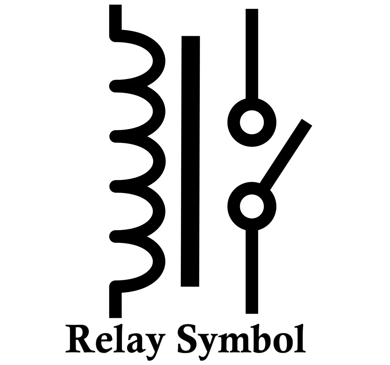
- A coil winding (inductor symbol)
- A movable switch contact with two terminals
Generic relay symbols:
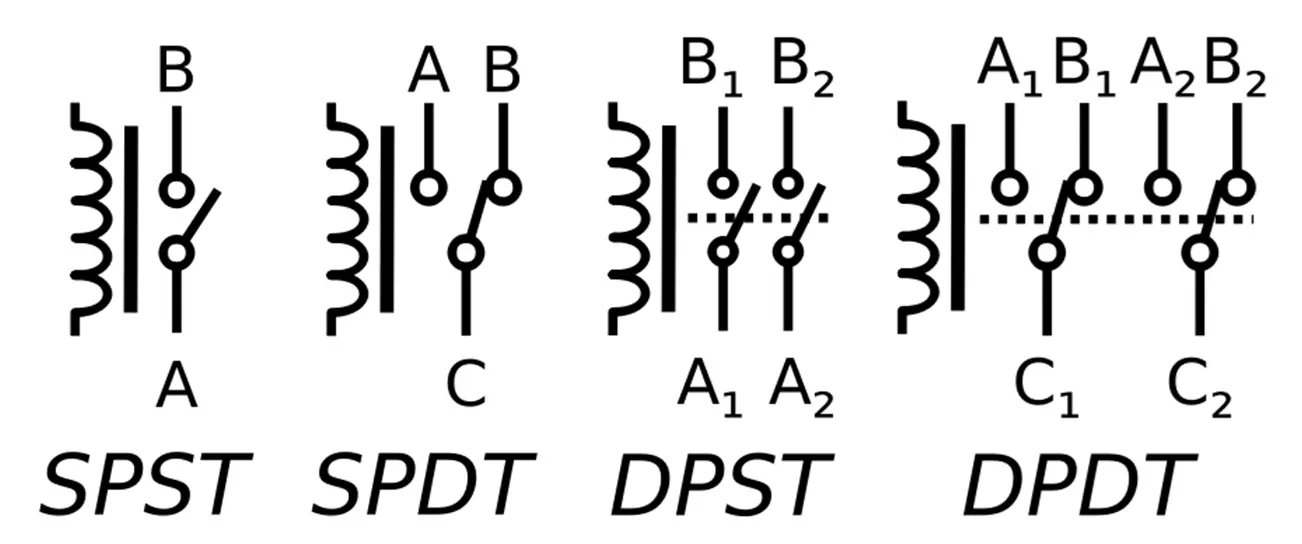
- Double Pole
- When coil energizes → A connects to B
- Double Throw
- B = contact closed by default
- A = contact open by default
- When coil energizes → C connects to A
Construction of Electromechanical Relay
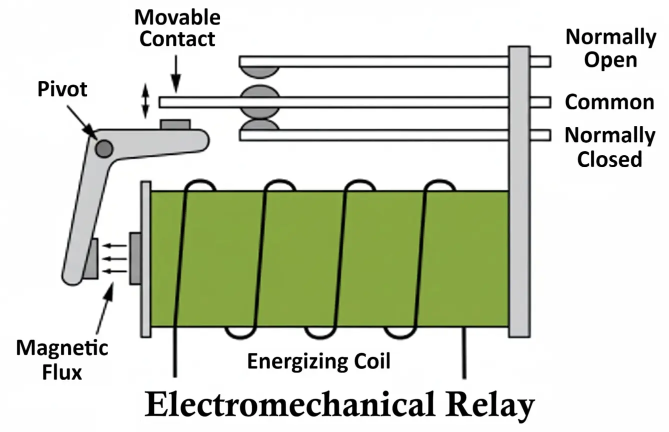
A typical relay consists of:
- Electromagnet Coil – copper wire wound on soft iron core; generates magnetic field when energized
- Armature (moving iron lever) – metal lever that physically moves when magnetic field pulls it
- Spring – returns armature to default / relaxed position when coil power is removed
- Stationary Contacts – fixed metal contacts → typically NO & NC terminals
- Moving Contact – mounted on the armature; moves to touch NO or NC depending on coil state
- Enclosure / Housing – plastic shell to protect internals from dust, humidity, contamination
- Terminals / Pins – external pins for coil and load switching (COM, NO, NC + coil pins)
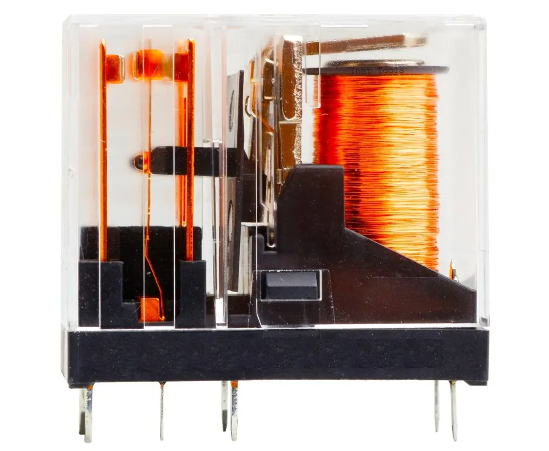
Modern PCB relays have 5 pins: (Coil pins A and B, COM, NO, NC).
When coil is OFF → moving contact rests on NC
When coil is ON → magnetic field pulls armature → moving contact flips to NO
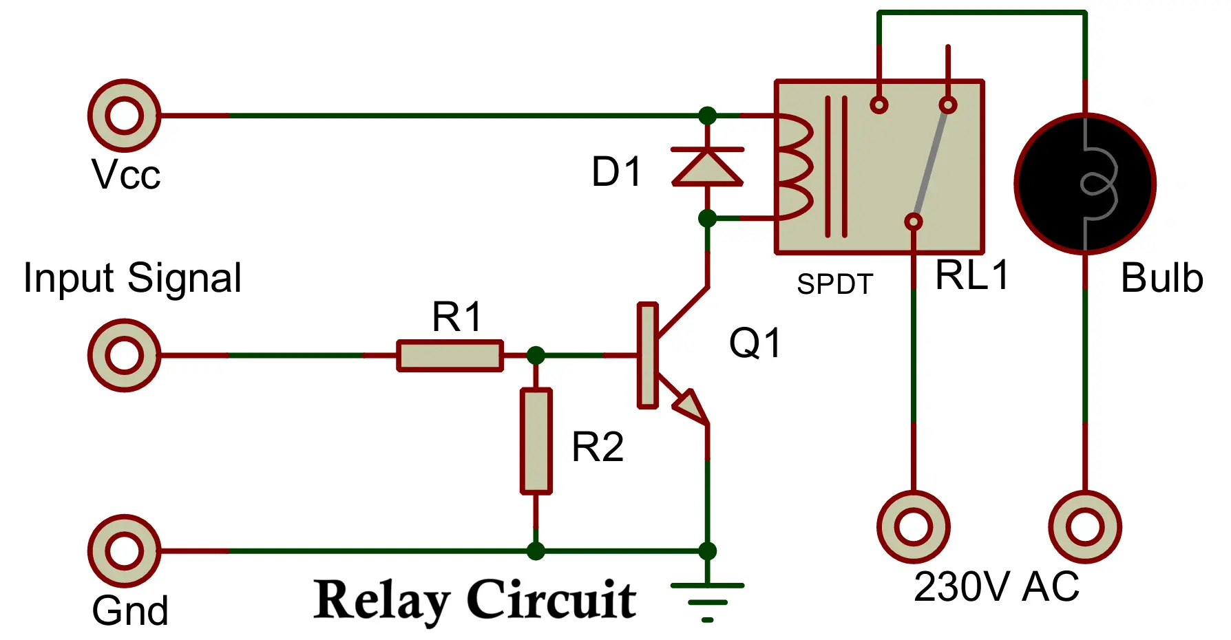
Relay Circuit Diagram (Control and Output)
Coil Driving Side: It is a low voltage DC control signal either from:
- Microcontroller output (ESP32, Arduino, PIC, AVR)
- Comparator output
- Logic circuit output
- Sensor controlled transistor
Usually, the relay coil is not directly driven by microcontroller because coil requires 30-80mA typically. So, a transistor driver + flyback diode is used.
Load Side:
- Load supply is isolated from coil supply
- AC or DC load can be switched
Working of Relay Circuit
In de-energized state:
- No current in the coil
- Armature rests in default NC position (spring tension)
- COM → NC is connected
When input 5-V DC signal energizes coil using transistor driver:
- Coil produces magnetic flux
- Magnetic field attracts armature
- Armature moves → breaks NC
- COM now connects to NO
- Output side gets 240V AC where the load is connected.
When the input 5V signal turns OFF:
- Coil demagnetizes
- Spring pulls armature back
- Contact returns to NC
- Load is disconnected and stops working.
Thus, relay offers electrical isolation between control and output circuits.
Specifications of Relay
Important parameters of an electromechanical relay:
| Parameter | Explanation |
|---|---|
| Coil rated voltage | 5V, 6V, 9V, 12V, 24V common |
| Coil resistance | determines coil current |
| Contact rating | e.g. 10A/250VAC, 7A/30VDC |
| Switching time | typically 5ms – 15ms |
| Contact form | SPST, SPDT, DPDT etc. |
| Isolation | coil-output dielectric strength |
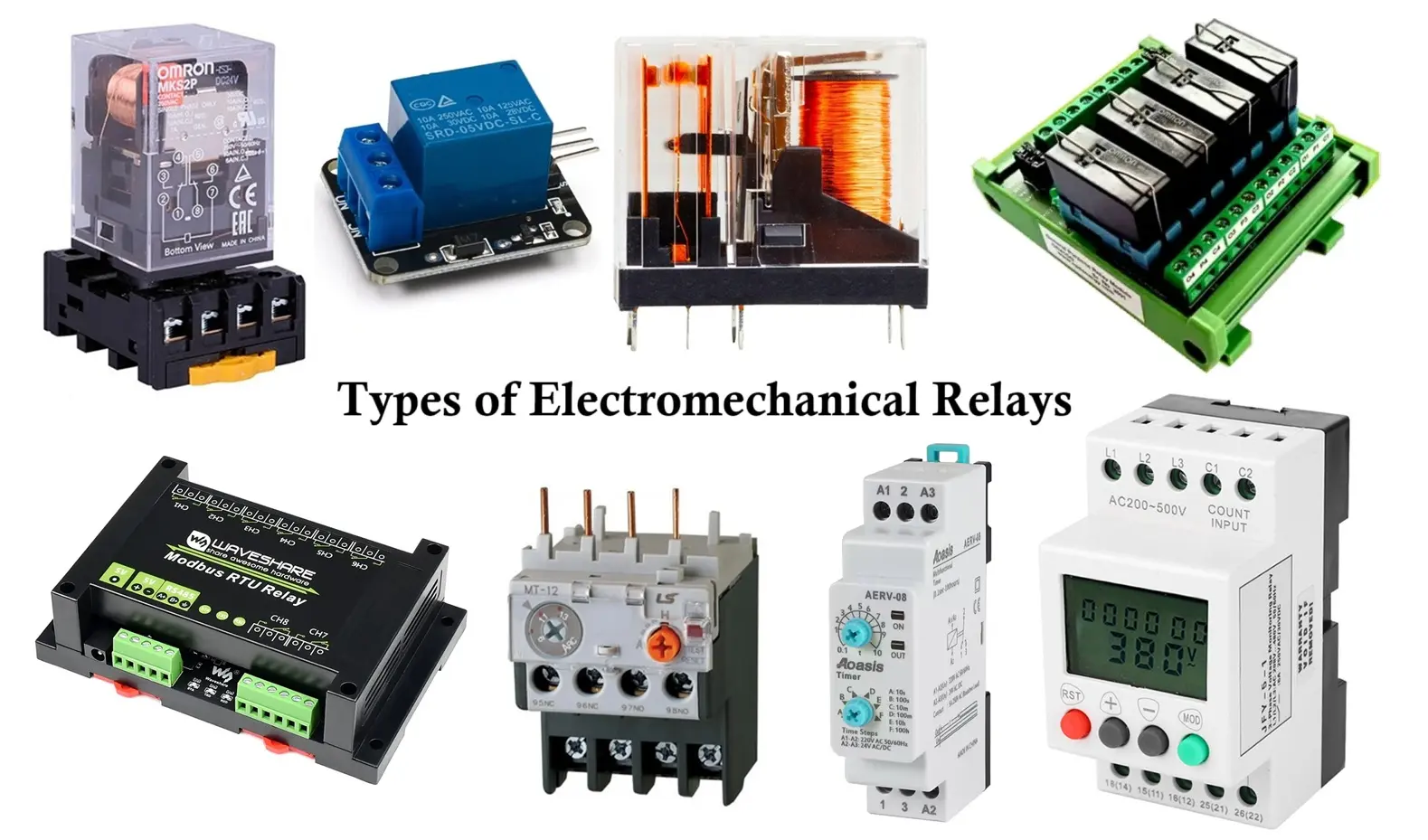
Types of Electromechanical Relays
Electromechanical relays are commonly classified by:
- Supply type (AC/DC)
- Operating principle (current / voltage / directional / distance / differential etc.)
- Time behavior (instantaneous / definite / inverse)
- Contact form (NO / NC / changeover)
- Pole–throw topology (SPST / SPDT / DPDT etc.)
- Special construction (reed / polarized / latching / Buchholz)
- Applications (motor control / protection / PLC interface / automotive / safety / building control)
1. Based on Supply Type
- DC relay
- coil is fed from DC
- armature simply pulls when DC builds flux
- AC relay
- coil fed by AC
- uses a shading coil / shading ring to prevent “chatter” at zero crossings
2. Based on Operating Principle
- current relay
- works when current exceeds pickup
- typical in overcurrent protection
- voltage relay
- works when voltage crosses threshold (OV or UV)
- power relay
- senses real or reactive power product (V×I×cosφ)
- directional relay
- compares current and reference voltage angle
- can detect direction of fault energy flow
- impedance relay
- operates on Z = V / I
- used in distance protection
- reactance relay
- operates only on reactance component (X)
- Mho relay
- operates on admittance characteristics
- inherently directional, very common in transmission line distance protection
- frequency relay
- trips on over or under frequency
- grid stability control
- differential relay
- compares currents at two ends of protected zone
- excellent selectivity (transformer / generator / bus protection)
- temperature relay
- thermal model or sensor (bimetal / RTD) triggers when temp increases
3. Based on Time Behavior
- instantaneous relay
- no intentional delay
- trips immediately when pickup reached
- definite time / time-lag relay
- fixed time delay after pickup regardless of magnitude
- inverse time relay
- higher the fault → quicker it trips
- used for coordination
- very inverse / extremely inverse
- steeper curve for high fault discrimination in distribution feeders
4. Special Construction Types
- reed relay
- sealed glass tube with ferromagnetic reeds
- used for very low current signalling, clean contacts
- polarized relay
- uses a permanent magnet for high sensitivity
- latching relay
- stays in last state even after coil power removed
- good for energy saving states
- Buchholz relay
- purely electromechanical gas-actuated float type
- transformer internal fault detection (gas from decomposition)
5. Based on Contact Structure
- normally open (NO / Form-A)
- contact closes when coil energized
- normally closed (NC / Form-B)
- contact opens when coil energized
- changeover / transfer (Form-C)
- both NO + NC — armature switches between two throws
6. Based on Poles and Throws
pole = number of circuits
throw = number of selectable contact outputs per pole
- SPST
- single pole, single throw
- one circuit switched, only ON / OFF
- simplest
- SPDT
- single pole, double throw
- one pole can connect to either of two output contacts
- common in control logic / changeover
- DPST
- double pole, single throw
- two separate circuits switched together
- used when you need to break two lines at once (e.g. both sides of supply)
- DPDT
- double pole, double throw
- two independent changeover circuits in one relay
- most flexible — often used in transfer/control
7. Based on Applications
- Motor control relays
- used in DOL starters / star-delta starters
- coil energized by control circuit → switches power contacts
- includes thermal overload relay in motor protection chain
- Lighting control relays / building automation relays
- large commercial buildings
- low-power switch in wall → high-power lighting feed handled by relay
- Protection relays (power system protection)
- transmission / sub-transmission / distribution
- purpose = detect fault + trip breaker
- examples → overcurrent, differential, distance, directional, UV/OV, freq
- Supervisory relays / auxiliary relays
- work in control logic
- interlocking, seal-in, coil supervision, alarm annunciation
- Switching relays in PLC / SCADA I/O interfacing
- PLC digital output can’t switch high voltage → relay is the interface
- typical in RTU panels, relay racks
- Automotive relays
- horn, fuel pump, headlights, ECU power
- rugged, compact, often sealed
- Telecom / signal relays
- very low contact current
- used for signal routing, multiplexing, audio switching (old exchange tech)
- Safety / emergency relays
- emergency stop circuits (E-stop)
- safety relay modules for machinery
- force-guided contact design so failure is detectable
- Metering / measurement relays
- used inside test benches / labs
- for switching reference sources, function generators, etc.
- HV switchgear trip relays
- final “trip coil drive” element
- in breaker control circuits — these are literally the last element before CB trip coil
Advantages of Electromechanical Relays
- True galvanic isolation between coil side & load side (kilovolts of isolation possible depending on model)
- Can switch AC or DC loads (unlike SCR/triac-only SSR types)
- Very high voltage + high current capability kA industrial contactors are literally relays
- Extremely intuitive operation (mechanical contact is easy to reason about)
- Intrinsic fail-safe state – open contact is physically visible/measurable
- Zero off-state leakage when contacts are open (SSR always leaks)
- Very cheap – globally available component
- Can handle inrush events better than MOSFET SSR (e.g., transformer / lamp surge)
- Relatively rugged against ESD / surge (coil is not static-sensitive)
- High dielectric isolation – ideal for HV DC battery pack systems
Disadvantages of Electromechanical Relays
- Finite mechanical lifetime (contact erosion, spring fatigue)
- Slow switching speed (milliseconds vs micro-nanoseconds for MOSFET/SCR)
- Coil consumes nontrivial power and generates heat (esp. latching vs non-latching)
- EMI / arcing noise — needs snubber / flyback diode for clean designs
- Contact bounce → needs debounce hardware or software
- Cannot run at high frequency PWM (not suitable for switching regulators)
- Bulkier & heavier vs SSR / MOSFET relays
- Can weld contacts under extreme surge or short-circuit conditions
- Audible clicking is undesirable in low-noise environments
Applications of Electromechanical Relays
- Power supply protection (OVP / OCP / battery disconnect)
- Industrial motor start / stop (contactors, DOL starters)
- SMPS mode switching (standby ↔ active load bypass)
- Lighting automation (street lights, building BMS)
- HV DC isolation in energy systems (EV pack relays, solar combiner relays)
- UPS / inverter transfer switching
- PLC I/O module output switching
- Home appliances (fridge, AC compressor, washing machine motor switching)
- Automotive systems (12 V / 24 V) headlights, fuel pump, radiator fan, horn. starter relay (solenoid)
- Security / alarm systems (siren driver, zone isolation)
- Generator set control panels
- Industrial sequencing / interlock logic (classic relay ladder logic)
In modern electronics, relay modules are heavily used along with microcontrollers for controlling mains appliances safely.
Electromechanical Relay vs Solid State Relay
Here is table showing all the differences between Electromechanical Relay and Solid State Relay EMR vs SSR.
| Parameter | Electromechanical Relay (EMR) | Solid State Relay (SSR) |
|---|---|---|
| Switching element | Mechanical metal contacts | Semiconductor (Triac / MOSFET / IGBT) |
| Isolation method | Air gap / physical spacing | Optocoupler |
| Switching speed | Slow (5–15 ms) | Very fast (µs – ns) |
| Contact wear | Yes (mechanical erosion) | No mechanical wear |
| Heat dissipation | Low coil heat only | Device heats more under load |
| Leakage current (OFF) | Almost zero (true galvanic isolation) | Has leakage (never 0) |
| Audible noise | Clicks during switching | Silent switching |
| EMI noise | Arc can produce spikes | Very low EMI |
| Suitable for PWM | No | Yes |
| Cost | Cheaper | More expensive |
| Best for | General control, high surge loads | High speed switching, automation, no-noise areas |
Conclusion
Electromechanical relay is a reliable, robust and universal switching device used for electrically isolating control signals from high power loads. The basic internal structure is simple – coil + armature + contacts – but its capability to switch AC/DC loads with complete isolation makes it irreplaceable in many applications. Although solid state relays and MOSFETs are gaining popularity, electromechanical relays still dominate where cost, isolation and high current capability are primary requirements.
Solid State Relay SSR – Symbol, Circuit, Construction, Working, Types and Applications
What is a Sensor? Types of Sensors, Classification & Applications
Different Types of Inductors Their Properties and Applications
Types of Transistors: Classification (BJT, JFET, MOSFET & IGBT)
