A Clipper Circuit, also called a limiter, is an electronic circuit that removes or “clips” selected portions of an input signal without distorting the remaining waveform. Its primary purpose is to prevent a signal from rising above or falling below a specified voltage level. Because of this, clippers are widely used in waveform shaping, signal conditioning, and overvoltage protection.
Clipper circuits operate by using nonlinear components – most commonly diodes, Schottky diodes, and Zener diodes which either block current flow or short the signal during specific portions of the waveform. Depending on the diode orientation and any applied bias voltages, clippers can limit positive peaks, negative peaks, or both.
Although a simple half-wave rectifier removes an entire half-cycle of an AC waveform, clipper circuits are generally more controlled. They are designed to limit only selected portions of the voltage, flattening or cutting off a defined range while leaving the rest of the signal unchanged.
Clipper circuits play an essential role in analog electronics and protection systems. They shape waveforms, restrict voltage amplitude, and safeguard sensitive components. You will find them used in audio electronics, communication systems, RF and radar equipment, microcontroller and logic-level protection, instrumentation circuits, and power electronics anywhere precise voltage limiting is required.
Working of Diode Clipper Circuit
To understand how clippers work, it is important to recall the basic operation of a diode:
- When a diode is forward biased, it conducts with a voltage drop of about 0.7V for silicon or 0.3V for germanium.
- When the diode is reverse biased, it theoretically blocks current flow, and the full voltage appears across its terminals.
Clipper circuits utilize this switching behavior. When the input voltage exceeds the diode’s forward or reverse threshold, the diode conducts and clamps the voltage. When the voltage is within the desired level, the diode remains reverse biased and the input waveform passes unchanged.
Although clipper circuits can work with any waveform, analysis is typically done using a sinusoidal input since it clearly illustrates how clipping changes waveform peaks. The clipped output often resembles a “flattened” or “leveled” version of the input, depending on the direction and type of clipping.
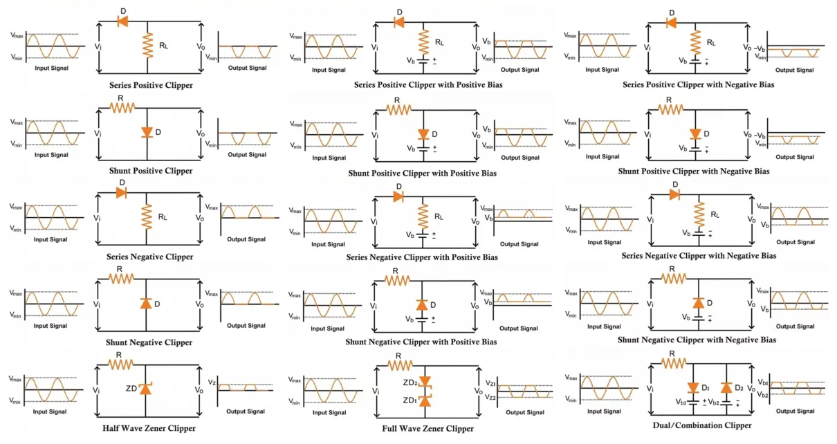
Types of Clipper Circuits
- Series Clippers
- Shunt Clippers
- Positive and Negative Clippers
- Biased Clippers
- Dual or Combination Clippers
- Zener Diode Clippers
Clippers are broadly categorized based on diode placement, polarity of clipping, and whether bias voltages are added to shift clipping thresholds. Each type has its own characteristics, advantages, and applications.
- Placement of Diode:
- Series Clipper
- Shunt Clipper
- Polarity of Clipping:
- Positive Clipper
- Negative Clipper
- Biasing:
- Unbiased Clipper
- Biased Clipper (Positive or Negative Bias)
- Dual Clippers (Combination Clippers)
- Zener Diode Clippers
- Half-Wave Zener Clipper
- Full-Wave Zener Clipper
Series Clipper Circuits
In a series clipper, the diode is placed directly in series with the load resistor. Because of this placement, the output signal depends entirely on whether the diode is conducting.
- When the diode is forward biased, it allows the input signal to reach the output.
- When the diode is reverse biased, it prevents current flow, so the signal is blocked.
This type of clipper is generally categorized into positive and negative series clippers.
Series Positive Clipper Circuit
A series positive clipper is designed to eliminate the positive half-cycle of the input waveform. In this configuration, the diode is oriented, so it becomes reverse biased when the input voltage moves positive.
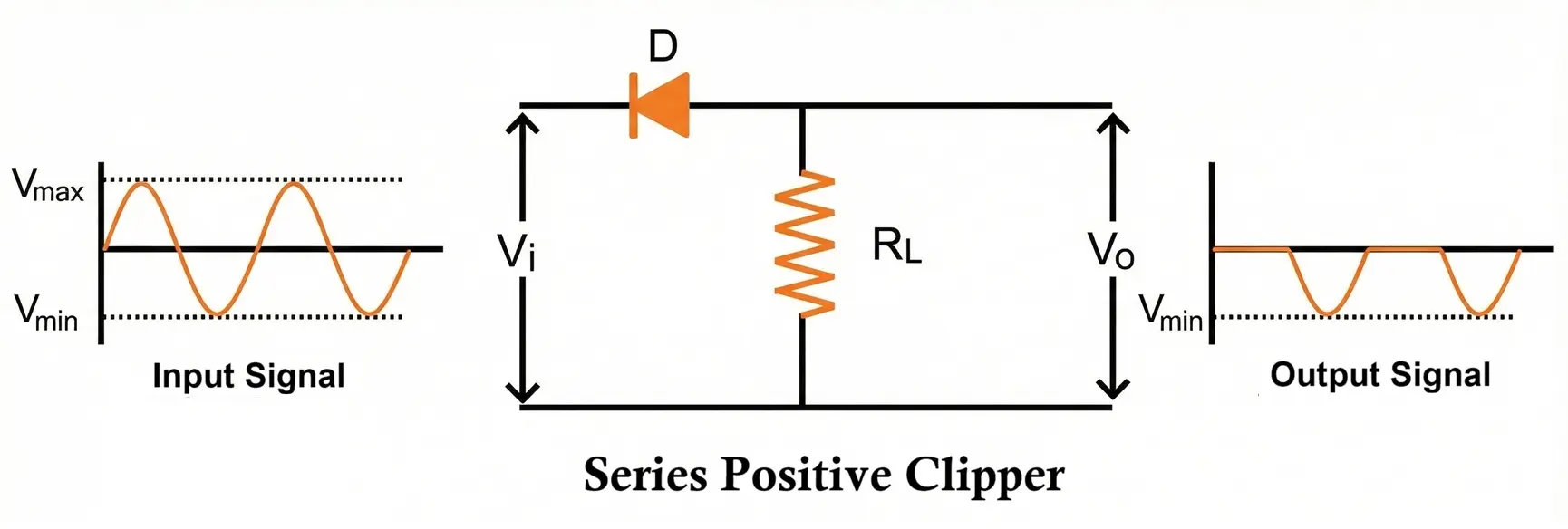
When the input signal Vi is applied:
- Positive Half-Cycle
- Point A becomes more positive than point B.
- The diode is reverse biased and cannot conduct.
- With no current through the load resistor RL, the output voltage remains zero.
- Therefore, the positive portion of the input does not appear at the output.
- Negative Half-Cycle
- Point A becomes more negative than point B.
- The diode becomes forward biased and current flows.
- The entire negative half-cycle appears across the load.
Thus, the circuit blocks the positive half of the waveform and passes the negative half unchanged.
Series Positive Clipper Circuit with Bias
Biasing is introduced when only part of a half-cycle needs to be clipped rather than the entire half. A series clipper can include a positive or negative bias source to shift the clipping level upward or downward.
Positive Bias
In a positively biased series clipper, the battery’s positive terminal is connected to the diode’s +ve P-side.
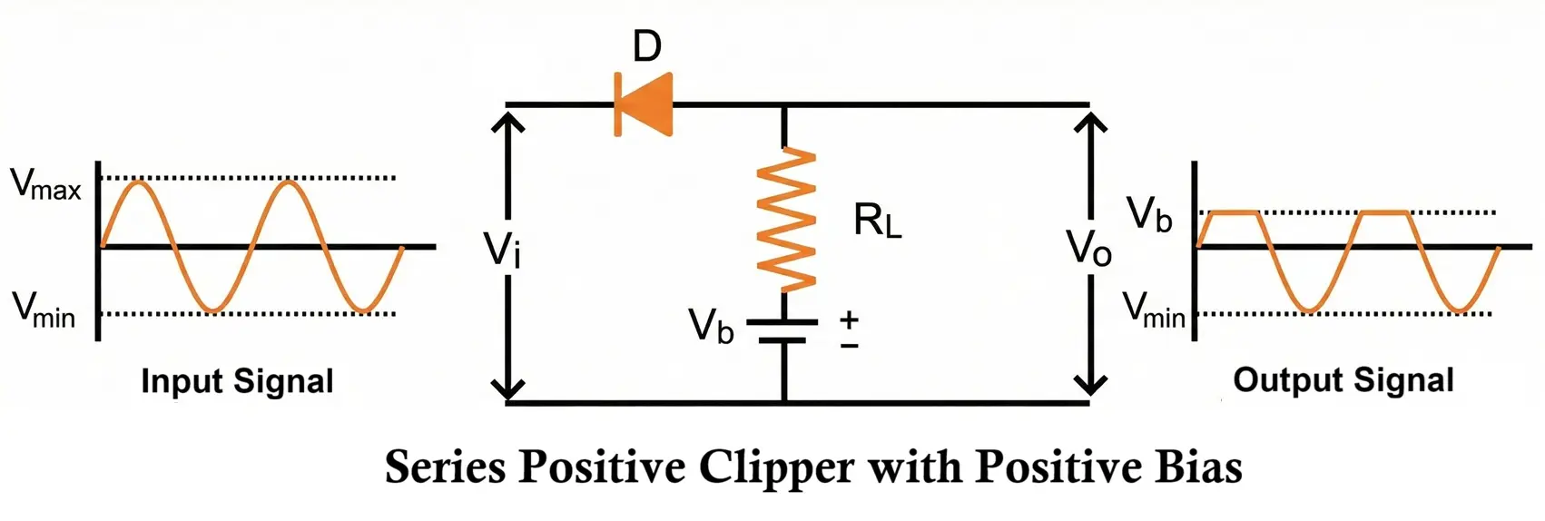
- Positive Half-Cycle
- The input attempts to reverse bias the diode.
- However, the bias source keeps the diode forward biased as long as the input voltage remains below the bias voltage.
- When the input voltage exceeds the bias value, the diode becomes reverse biased and stops conducting.
- As a result, the output stays limited to the bias voltage ( Vb ) during high positive inputs.
- Negative Half-Cycle
- Both the negative input and the battery help forward bias the diode.
- The diode conducts freely, and the negative portion of the signal appears at the output.
This configuration clips the waveform only above a certain positive threshold.
Negative Bias
In the negatively biased version, the battery polarity is reversed relative to the diode.
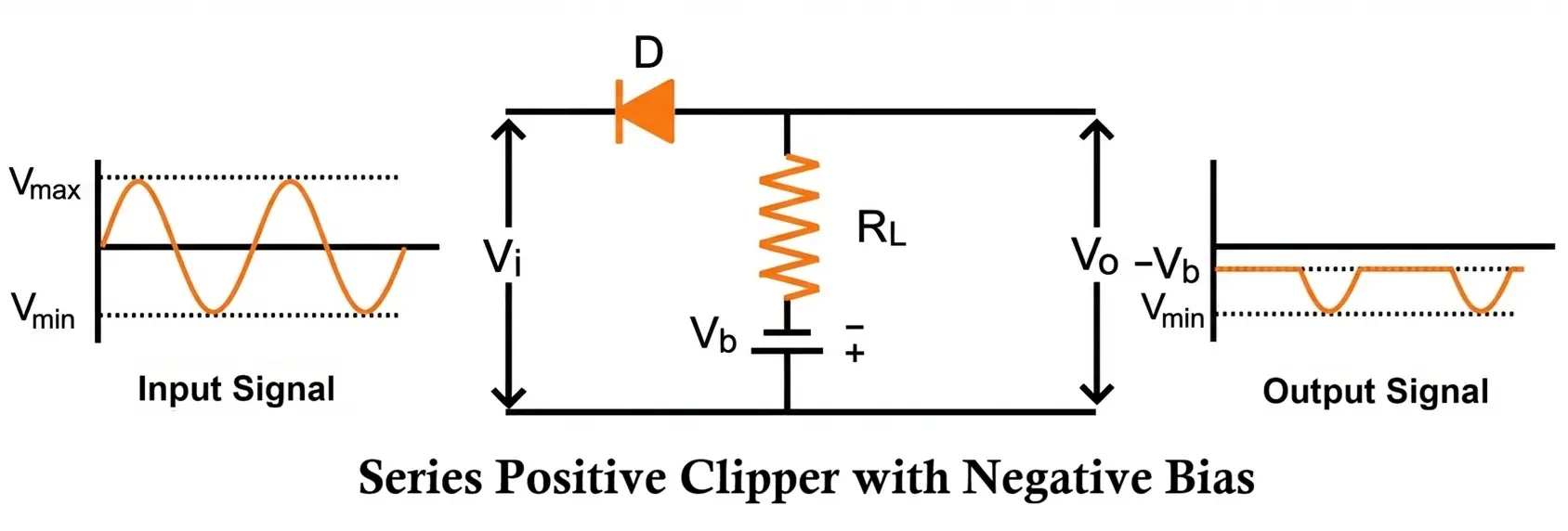
- Positive Half-Cycle
- The input and the negative bias voltage both reverse bias the diode.
- Because conduction is blocked, the diode remains off.
- The output shows only the negative battery voltage, acting as a reference clipping level.
- Negative Half-Cycle
- The input voltage now tends to forward bias the diode.
- But the negative bias opposes conduction.
- Only when the input voltage becomes more negative than the battery voltage does the diode conduct.
- If the input does not exceed this threshold, the output remains equal to the negative battery voltage.
This arrangement clips at a lower, shifted level on the negative side of the waveform.
Series Negative Clipper Circuit
A series negative clipper removes the negative half-cycle of the input signal. The diode is oriented so that it conducts during the positive half of the waveform and blocks during the negative half.
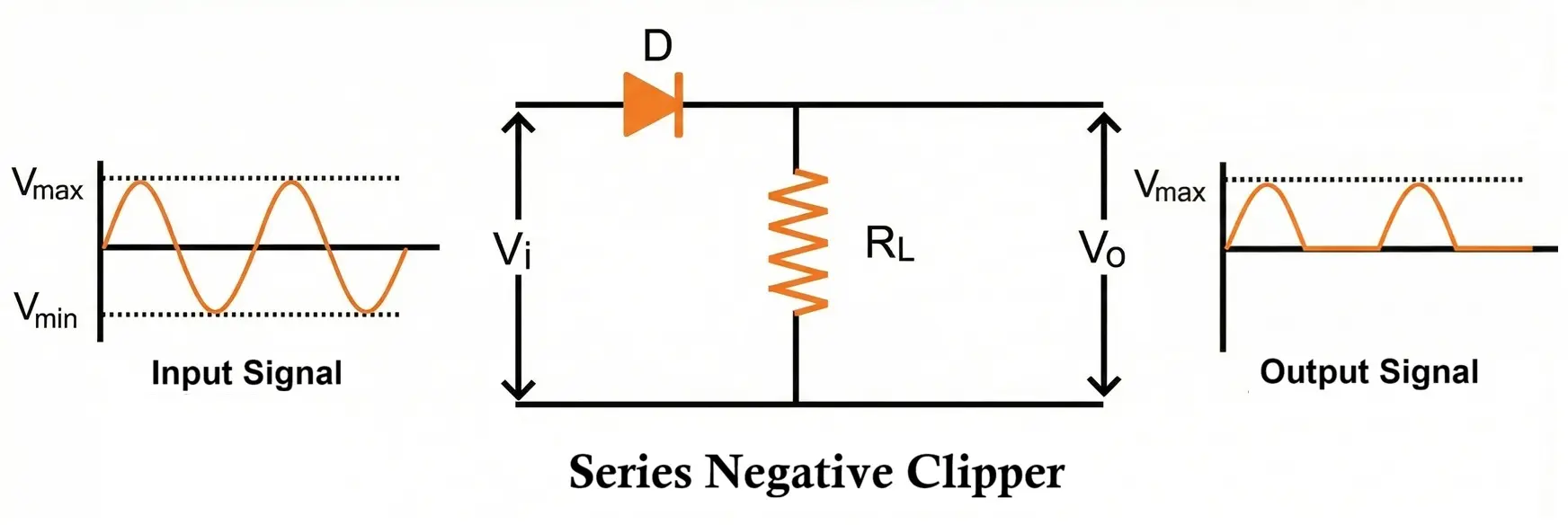
Operation
- Positive Half-Cycle
- As the input voltage becomes positive, the diode is forward biased.
- Current flows through the diode, so the input waveform appears across the load resistor.
- The output faithfully follows the positive half-cycle.
- Negative Half-Cycle
- When the input swings negative, the diode becomes reverse biased.
- Since no current flows, the output drops to zero (or nearly zero).
- Thus, the entire negative half-cycle is clipped from the waveform.
This creates an output that contains only the positive portion of the input, with the negative portion completely removed.
Series Negative Clipper Circuit with Bias
Biasing is used when only part of the negative half-cycle needs to be clipped—rather than removing the entire negative swing. A bias voltage shifts the clipping level, allowing more controlled waveform shaping.
Two biasing types exist: positive bias and negative bias.
1. Positive Bias
In a positively biased series negative clipper, a battery is placed so its voltage opposes the forward biasing of the diode during the positive half-cycle.
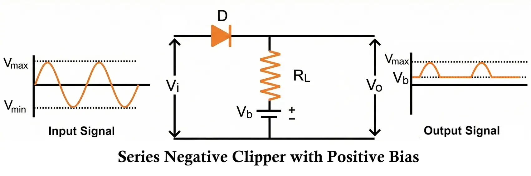
- Positive Half-Cycle
- The input voltage tries to forward bias the diode.
- The battery voltage acts in the opposite direction and tries to reverse bias it.
- The diode conducts only when the input voltage becomes greater than the battery voltage.
- At lower input voltages, the diode remains off, and the battery voltage alone appears at the output.
- Negative Half-Cycle
- During the negative swing, both the input and the battery reverse bias the diode.
- The diode remains non-conducting throughout the entire negative half-cycle.
- Therefore, the output remains fixed at the battery voltage for all negative input values.
This configuration effectively clips the waveform at a more positive threshold, determined by the bias voltage.
2. Negative Bias
Here, the battery is connected so that it helps forward bias the diode during positive inputs.
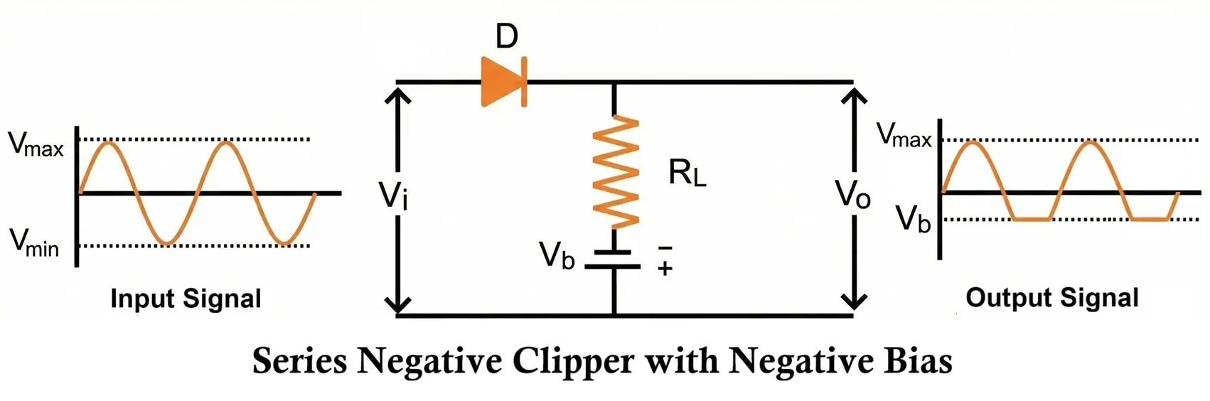
- Positive Half-Cycle
- The input voltage and the negative bias voltage both forward bias the diode.
- Because of this combined effect, the diode conducts over the entire positive half-cycle.
- The output follows the positive input waveform exactly.
- Negative Half-Cycle
- The negative input attempts to reverse bias the diode.
- However, the negative battery voltage still tries to forward bias it.
- As long as the battery voltage is greater in magnitude than the input, the diode remains forward biased and conducts.
- When the input becomes more negative than the bias source, the diode finally switches off.
- At that point, the output equals the battery voltage instead of the input.
This shifts the clipping level deeper into the negative region, giving controlled, partial clipping of the negative half-cycle.
Shunt Clipper Circuits
In a shunt clipper, the diode is placed in parallel with the load resistor. The operation of the circuit depends on whether the diode is conducting or blocking:
- When the diode is forward biased, it provides a low-resistance path and effectively shorts the signal, preventing it from appearing at the output.
- When the diode is reverse biased, it does not conduct, so the input waveform appears across the load.
Like series clippers, shunt clippers are grouped into positive and negative types, depending on which portion of the waveform is removed.
Shunt Positive Clipper Circuit
A shunt positive clipper removes the positive half-cycle of the waveform. The diode is oriented so that it conducts when the input voltage becomes positive.
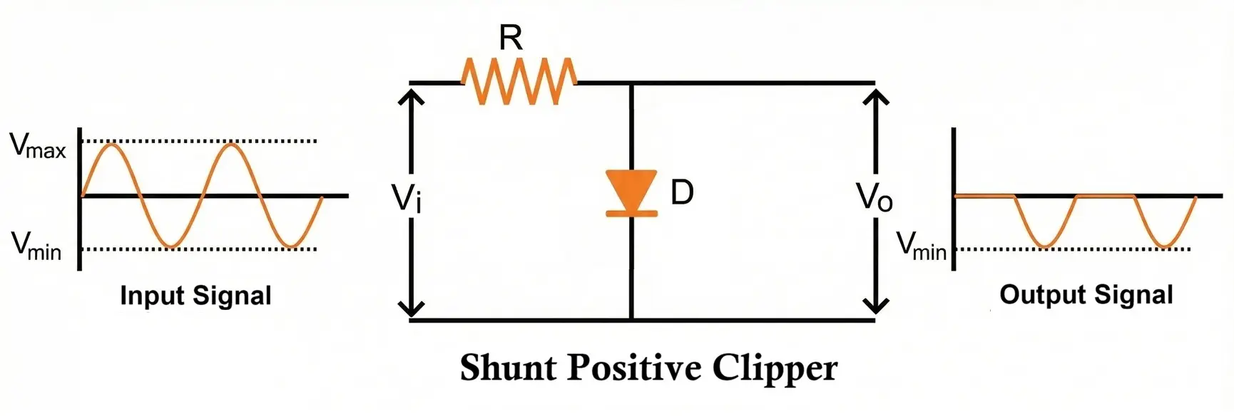
Operation
- Positive Half-Cycle
- Point A becomes more positive than point B.
- The diode becomes forward biased and conducts heavily.
- Because the diode essentially shorts the signal to ground, the output voltage becomes nearly zero.
- Thus, the positive portion of the waveform is eliminated.
- Negative Half-Cycle
- The polarity of the input reverses.
- The diode becomes reverse biased and stops conducting.
- The entire negative half of the signal appears across the load resistor.
In summary, the shunt positive clipper blocks the positive half-cycle and passes the negative half-cycle.
Shunt Positive Clipper Circuit with Bias
A bias voltage is added when the clipping level needs to be adjusted instead of clipping the entire half-cycle at 0 V. The bias source may be connected in either positive or negative orientation.
1. Positive Bias
A positively biased shunt clipper shifts the clipping level upward.
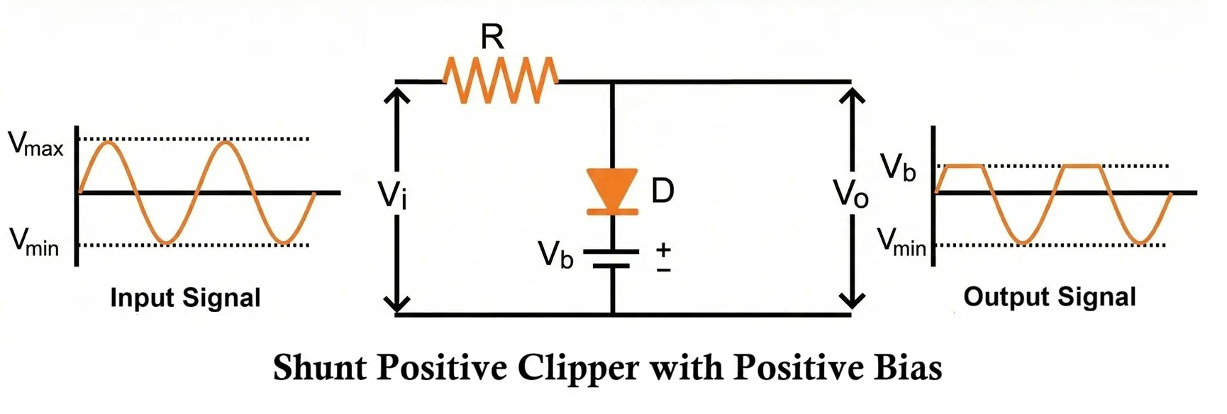
- Positive Half-Cycle
- The input signal tends to forward bias the diode.
- The bias voltage, however, tends to reverse bias it.
- The diode will conduct only when the input voltage exceeds the bias voltage.
- If the input voltage is lower than the bias, the diode stays off, and the input appears at the output.
- What Happens at the Output?
- When (Vin < Vb): diode off → output follows the input
- When (Vin > Vb): diode on → circuit clamps the output to the battery voltage
- Negative Half-Cycle
- The diode is reverse biased by both the input and the bias source.
- Therefore, the entire negative half-cycle keeps the output unchanged.
This configuration clips only the portion of the positive half-cycle that rises above the bias voltage.
2. Negative Bias
Here the battery is connected with reversed polarity, lowering the clipping threshold.
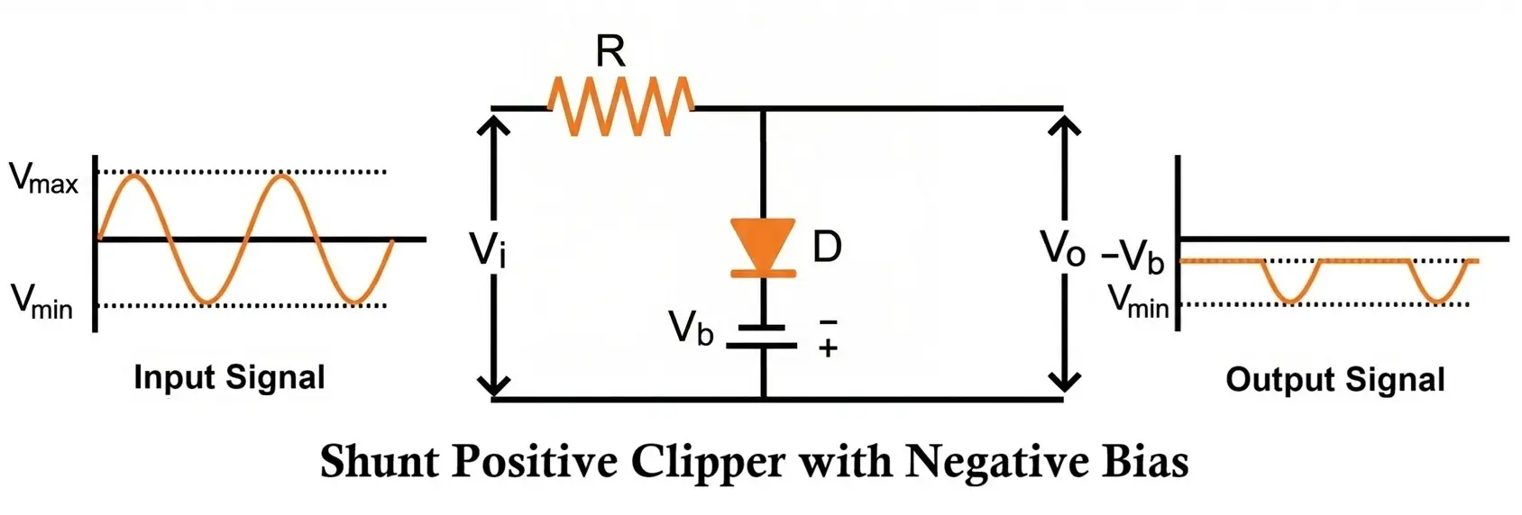
- Positive Half-Cycle
- Both the input and the negative bias forward bias the diode.
- The diode conducts throughout the entire positive half-cycle.
- As a result, the output remains at the battery voltage during this interval.
- Negative Half-Cycle
- The input tries to reverse bias the diode.
- The negative bias attempts to forward bias it.
- Whether the diode conducts depends on their combined effect:
- If the magnitude of the input voltage is less than the bias voltage, the diode remains forward biased and the output equals the battery voltage.
- When the input becomes more negative than the bias, the diode becomes reverse biased and the input waveform appears at the output.
This setup clips the signal at a shifted negative level, depending on the bias voltage.
Shunt Negative Clipper Circuit
A shunt negative clipper removes the negative half-cycle of the input waveform. The diode is placed in parallel with the load so that it conducts during the negative swing and blocks during the positive swing.
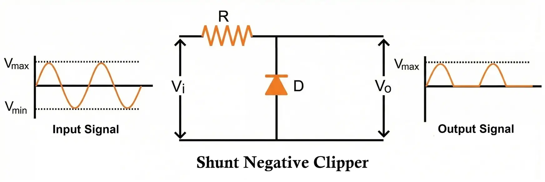
Operation
- Positive Half-Cycle
- As the input voltage becomes positive, the diode is reverse biased.
- Because the diode cannot conduct, the input voltage appears directly across the load resistor.
- Therefore, the positive half-cycle passes through unaffected.
- Negative Half-Cycle
- When the input voltage goes negative, the diode becomes forward biased.
- The diode provides a low-resistance path, effectively shorting the signal.
- As a result, the output voltage drops to nearly zero, removing the negative portion of the waveform.
Thus, the shunt negative clipper passes the positive half and clips the negative half of the input signal.
Shunt Negative Clipper Circuit with Bias
A bias voltage can be added to adjust the clipping level so that only part of the negative half-cycle is clipped rather than clipping it entirely. By using a battery in either orientation, we obtain a positively biased or negatively biased shunt negative clipper.
1. Positive Bias
With positive biasing, the battery is connected so that it tends to forward bias the diode even when the input is positive.
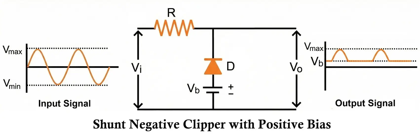
- Positive Half-Cycle
- The input signal reverse biases the diode.
- The battery forward biases it.
- The diode will remain forward biased as long as the input voltage is less than the bias voltage.
- When the input exceeds the battery voltage, the diode becomes reverse biased and stops conducting, and the input waveform appears at the output.
- Behavior at the Output
- When (Vin < Vb): diode conducts → output equals the battery voltage
- When (Vin > Vb): diode blocks → output follows the input
- Negative Half-Cycle
- Both the negative input and the battery voltage forward bias the diode.
- The diode conducts throughout the entire negative half-cycle.
- Therefore, only the battery voltage appears at the output for the whole negative swing.
This arrangement shifts the clipping level upward from zero to the bias voltage.
2. Negative Bias
In a negatively biased shunt negative clipper, the battery is connected in the opposite direction, pushing the clipping threshold downward.
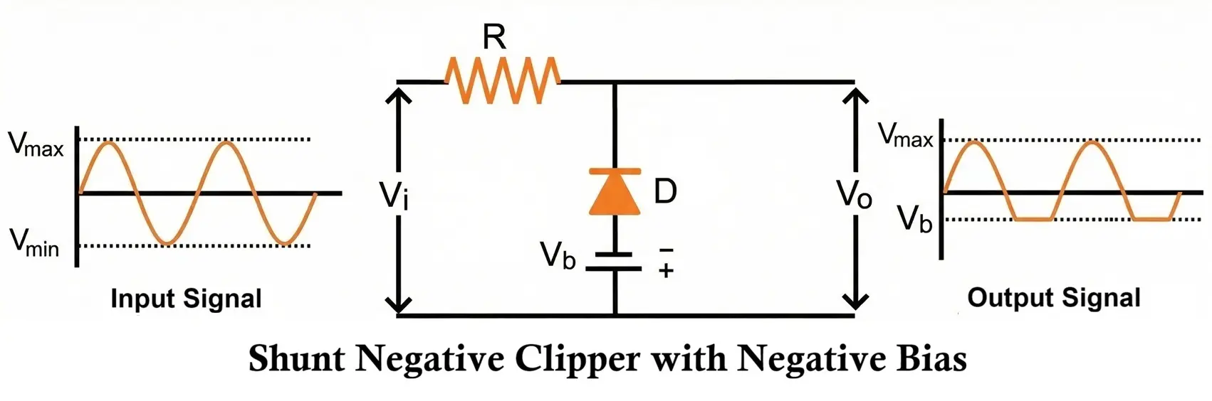
- Positive Half-Cycle
- The input voltage and the negative bias source both reverse bias the diode.
- The diode remains non-conducting.
- Consequently, the entire positive half-cycle appears across the load.
- Negative Half-Cycle
- The input tends to forward bias the diode.
- The negative battery opposes this and tends to reverse bias it.
- The diode will conduct only when the input voltage magnitude becomes greater than the battery voltage.
- When the diode conducts, the output clamps to the battery voltage.
- Output Summary
- When (Vin < Vb): diode off → output follows input
- When (Vin > Vb): diode on → output equals battery voltage
This setup allows controlled clipping at a more negative level, depending on the amount of bias applied.
Dual or Combination Clipper Circuit
A two-diode configuration can clip both the positive and negative halves of a waveform. This is often called a two-level or dual clipper:
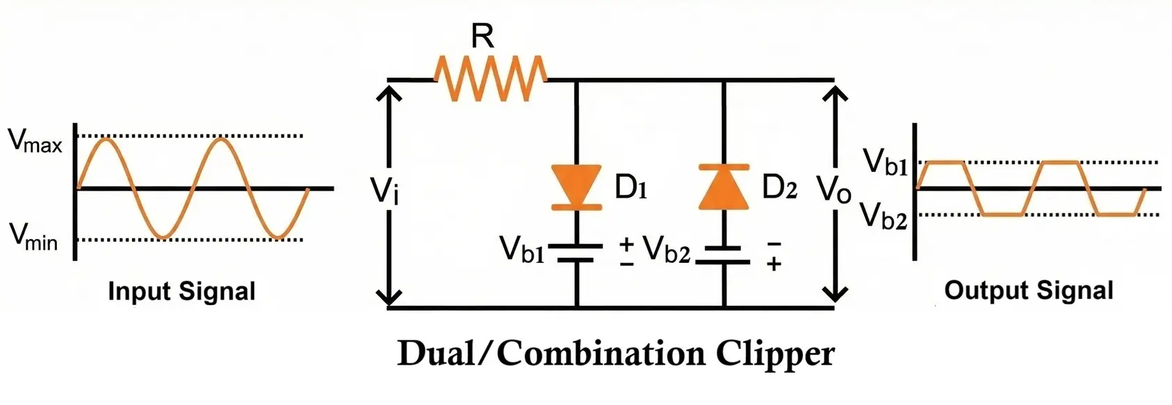
- One diode clips the positive peaks.
- The other diode clips the negative peaks.
Types
- Unbiased Dual Clipper
- Both diodes clip at 0 V (or diode drop).
- In an unbiased dual clipper using silicon diodes, clipping occurs at approximately ±0.7V.
- Biased Dual Clipper
- To increase or adjust clipping levels, either more diodes can be placed in series or bias voltages can be added.
- This allows clipping at any desired level, such as +5V and –4V, which is useful in signal shaping and limiter circuits.
Example
- Diode D1 clips positive peaks at +5 V
- Diode D2 clips negative peaks at −5 V
Output waveform is flat-topped above −5 V and +5 V.
Applications:
- Waveform limiting
- Signal conditioning
- Noise suppression
Biased clippers are essential when dealing with signals that must not exceed certain voltages, such as microcontroller inputs, power amplifier stages, and precision sensors.
Zener Diode Clipper Circuit
Zener diodes provide precise and stable clipping levels due to their sharply defined breakdown voltage without needing an external battery voltage. In reverse bias, the Zener diode conducts sharply at its breakdown voltage (VZ), maintaining a constant voltage regardless of current variations (within limits).
1. Half-Wave Zener Clipper
A single Zener diode clips one side of the waveform.
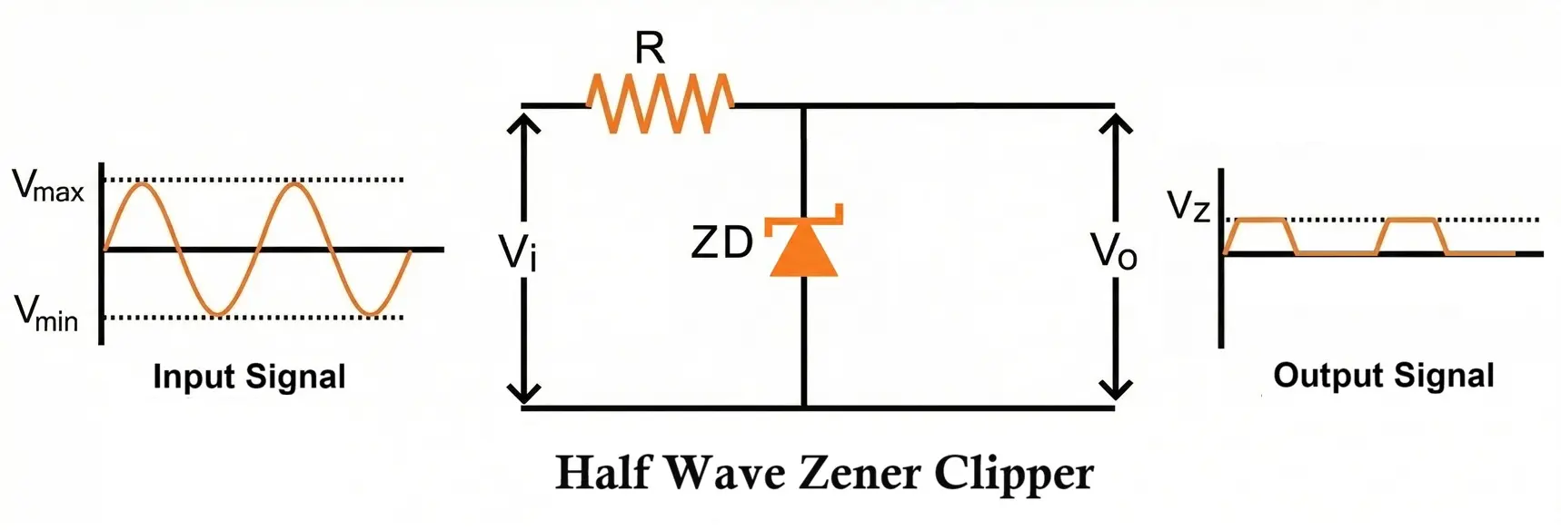
Operation
- Forward-biased side → clips at about +0.7 V
- Reverse-biased side → clips at Zener voltage (VZ)
Thus, clipping is asymmetric.
2. Full-Wave Zener Clipper
Uses two Zener diodes in opposite directions.
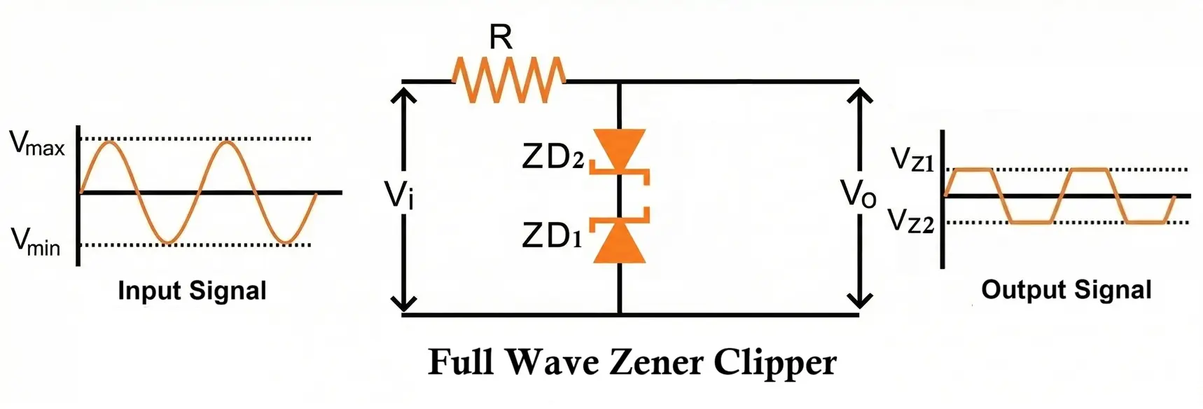
Operation
- Positive waveform clipped at +VZ
- Negative waveform clipped at −VZ
Advantages
- Very accurate clipping levels
- Symmetric waveform limiting
- Useful in voltage regulation, surge protection, and signal conditioning
They are widely used in:
- Surge protection
- Voltage regulation
- Signal limiting in ADC circuits
- Power-supply crowbar protection
A current-limiting resistor is mandatory to prevent excess current in Zener breakdown.
Waveform Behavior and Clipping Effects
When clipping occurs, the peaks of the sinusoidal waveform become flat or levelled, causing sharp transitions. Excessive clipping can turn a sine wave into a square wave, rich in harmonic content. This can be beneficial or harmful depending on application:
- In audio, clipping causes distortion (undesirable).
- In oscillators, it can generate square waves (useful).
- In power electronics, it protects components (essential).
- In communication circuits, clipping limits amplitude to avoid saturation.
The harmonics produced by clipping must be considered in analog signal processing, audio engineering, and EMI-sensitive designs.
Summary Table of 16 Types of Clipper Circuits
| Clipper Type | Diode Position | Polarity Clipped | Biasing Effect | Use Case Example |
|---|---|---|---|---|
| 1. Series Positive Clipper | Series | Positive | None | Removing unwanted positive spikes |
| 2. Series Positive Clipper (Positive Bias) | Series | Positive | Clips above +Vbias | Shift clipping to a higher level |
| 3. Series Positive Clipper (Negative Bias) | Series | Positive | Clips below –Vbias | Clip positive cycle deeper into negative region |
| 4. Series Negative Clipper | Series | Negative | None | Removing negative-going spikes |
| 5. Series Negative Clipper (Positive Bias) | Series | Negative | Clips above +Vbias | Modify negative clipping threshold |
| 6. Series Negative Clipper (Negative Bias) | Series | Negative | Clips below –Vbias | Shift clipping further negative |
| 7. Shunt Positive Clipper | Shunt | Positive | None | Shorting excessive positive voltages |
| 8. Shunt Positive Clipper (Positive Bias) | Shunt | Positive | Clips above +Vbias | Set a defined positive clipping level |
| 9. Shunt Positive Clipper (Negative Bias) | Shunt | Positive | Clips below –Vbias | Clip earlier in the positive cycle |
| 10. Shunt Negative Clipper | Shunt | Negative | None | Protect against negative voltage surges |
| 11. Shunt Negative Clipper (Positive Bias) | Shunt | Negative | Clips above +Vbias | Adjust negative clipping threshold upward |
| 12. Shunt Negative Clipper (Negative Bias) | Shunt | Negative | Clips below –Vbias | Set deeper negative clipping |
| 13. Dual (Unbiased) Clipper | Series/Shunt | Both | None | Clip signal at 0V on both ends |
| 14. Dual (Biased) Clipper | Series/Shunt | Both | Independent ±Vbias | Waveform shaping with two distinct clip levels |
| 15. Zener Diode Clipper (Half-Wave) | Series/Shunt | Positive or Negative | Zener breakdown on one side | Precise single-ended voltage limiting |
| 16. Zener Diode Clipper (Full-Wave) | Series/Shunt | Both | Symmetric ±VZ clipping | Accurate two-sided limiting for protection |
Applications of Clipper Circuit
Clipper circuits are used extensively in electronics to shape, limit, and protect signals. By removing portions of a waveform, they help ensure that circuits operate safely and that signals remain within desired voltage ranges.
1. Voltage Limiting and Protection
Clipper circuits prevent voltage levels from exceeding safe values.
- Protect sensitive components (transistors, op-amps, MOSFET gates) from overvoltage.
- Prevent voltage spikes from entering digital or analog circuits.
- Commonly used at the input of measuring instruments and communication devices.
2. Waveform Shaping
Clippers alter the shape of a signal by removing positive or negative peaks.
- Used to create flat-topped waveforms.
- Useful in signal conditioning before processing or amplification.
- Required in circuits where only specific voltage ranges must be retained.
3. Noise Reduction
High-frequency noise or unwanted spikes can be clipped off.
- Ensures stable operation of sensors and analog circuits.
- Provides smoother and less distorted signals for further amplification.
4. Digital Signal Restoration
In digital electronics, clippers help reshape noisy square waves.
- Removes voltage overshoot or ringing.
- Helps restore logic levels to clean HIGH and LOW states.
5. AM (Amplitude Modulation) Radio Receivers
Clippers are used in envelope detection and demodulation systems.
- They prevent excessive modulation from distorting the recovered audio.
- Improve the fidelity of the demodulated signal.
6. Power Supply Circuits
Clipper-type circuits appear in voltage regulators and reference generators.
- Zener diode clippers maintain fixed voltage levels.
- Provide protection against reverse polarity and transient surges.
7. Communication Systems
Clippers limit waveform amplitude to maintain signal integrity.
- Used in FM transmitters and receivers.
- Help maintain constant amplitude to avoid bandwidth expansion and distortion.
8. Waveform Slicing
Clippers can “slice off” portions of a waveform at precise voltage levels.
- Used in pulse shaping circuits.
- Essential in timing circuits and clock waveform modification.
9. Limiting Amplifiers
In audio and instrumentation systems:
- Clipper circuit restricts maximum amplitude before the signal enters an amplifier.
- Prevent distortions and protect speakers or sensitive measurement devices.
10. Comparator Reference Circuits
Biased clippers create reference voltages used in:
- Comparators
- Threshold detectors
- Trigger circuits (Schmitt triggers, multivibrators)
Conclusion
Clipper circuits are simple yet powerful tools in electronic design. By selectively removing or limiting specific portions of a waveform, they enable safe operation, clean signal processing, noise reduction, and precise voltage regulation. Diode clippers – whether series, shunt, biased, or Zener-based all are used in numerous applications ranging from audio electronics to power supplies, RF systems, digital logic protection, and waveform generation. Their reliability, simplicity, and versatility make them essential components in both analog and digital circuit design.
Voltage Multiplier Circuit Diagram, Working, Types and Applications
Schmitt Trigger Circuit Diagram, Working, Types and Applications
Different Types of Oscillators with Working and Applications
