Multiplexers (MUX) and Demultiplexers (DEMUX) are essential combinational logic circuits used in digital electronics for data transmission and communication systems. They play a crucial role in efficiently handling multiple signals by optimizing the usage of data lines, reducing hardware complexity, and enhancing the efficiency of data processing units. Let’s explore the difference between multiplexer and demultiplexer, with their types, advantages, disadvantages, applications, and commonly used ICs by circuit designers and engineers working with digital systems.
What is a Multiplexer (MUX)?
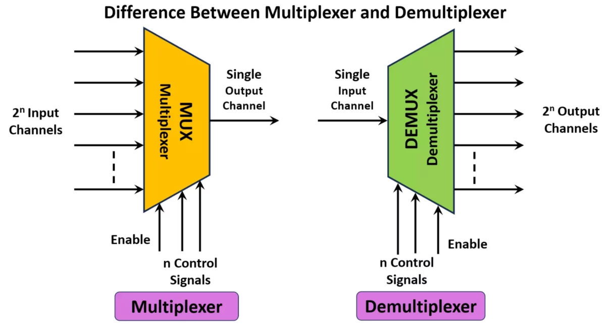
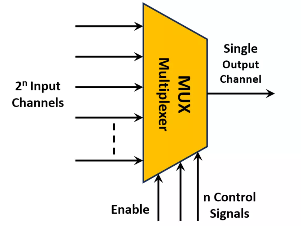
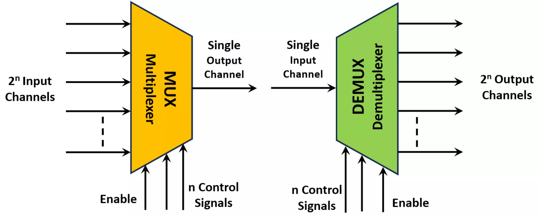
A multiplexer (MUX) is a combinational circuit that selects one of several input signals and forwards it to a single output line. It acts as a data selector and is controlled by a set of select lines. MUX is widely used in data routing and communication systems, enabling the efficient transmission of multiple signals over a single channel.
Types of Multiplexers
- 2:1 Multiplexer – Selects one of the two inputs based on a single select line.
- 4:1 Multiplexer – Selects one of four inputs with two select lines.
- 8:1 Multiplexer – Uses three select lines to choose one among eight inputs.
- 16:1 Multiplexer – Uses four select lines to select one of sixteen inputs.
- 32:1 and Higher Multiplexers – These are used in advanced applications where a large number of input signals need to be routed efficiently.
Advantages of Multiplexer
- Efficient use of communication channels by reducing the number of data lines required.
- Simplifies circuit design, making it easier to manage multiple signals.
- Reduces hardware requirements, leading to cost-effective solutions.
- Provides better synchronization of data transmission in digital systems.
- Enables multiple sensor data integration in IoT and embedded systems.
Disadvantages of Multiplexer
- Complex circuitry for higher order multiplexers, requiring additional logic gates.
- Delay in signal propagation due to circuit complexity.
- Can introduce noise and distortion in the transmitted signals, affecting data integrity.
- Requires additional processing power for handling high-speed data transmission.
What is a Demultiplexer (DEMUX)?
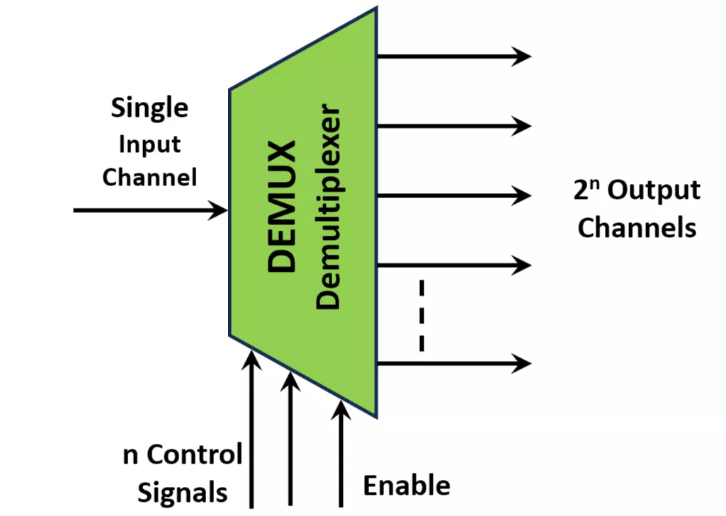
A demultiplexer (DEMUX) is a combinational circuit that receives a single input and distributes it over multiple output lines based on select signals. It acts as a data distributor and is commonly used in data routing and signal demodulation. DEMUX is crucial in scenarios where a single communication line carries multiple signals that need to be separated.
Types of Demultiplexers
- 1:2 Demultiplexer – One input is directed to one of two outputs based on a select line.
- 1:4 Demultiplexer – One input is directed to one of four outputs using two select lines.
- 1:8 Demultiplexer – Uses three select lines to distribute the input signal to one of eight outputs.
- 1:16 Demultiplexer – Uses four select lines to select one of sixteen outputs.
- 1:32 and Higher Demultiplexers – Used in complex systems where high-speed data needs to be distributed efficiently.
Advantages of Demultiplexer
- Efficient data routing reduces the complexity of communication systems.
- Reduces hardware complexity in circuits by enabling a single input to be distributed.
- Facilitates signal separation in communication systems, improving data accuracy.
- Reduces the need for multiple dedicated transmission lines, saving infrastructure costs.
- Enhances efficiency in multimedia streaming by distributing signals to multiple destinations.
Disadvantages of Demultiplexer
- Complexity increases with a higher number of output lines, requiring more control signals.
- Signal degradation and timing issues can arise in high-speed applications.
- Requires precise synchronization to avoid data loss or misrouting.
- Susceptible to noise and interference, affecting signal quality.
Applications of Multiplexer and Demultiplexer
Multiplexers (MUX) and Demultiplexers (DEMUX) are fundamental components in digital circuits, widely used in communication, computing, and signal processing.
1. Applications of Multiplexer (MUX)
A MUX selects one input from multiple inputs and forwards it to a single output.
1. Data Selection in Communication Systems
- Used in telecommunication networks to combine multiple signals into one transmission line, reducing hardware cost.
- Example: In telephone networks, multiple calls are transmitted over a single optical fiber using a MUX.
2. Data Routing in Microprocessors
- CPUs and microcontrollers use MUX to select data from different registers or memory locations.
- Example: A MUX can switch between RAM, ROM, and I/O devices based on control signals.
3. Arithmetic Logic Unit (ALU) Design
- MUX is used in ALUs to select different operations like addition, subtraction, AND, OR, etc.
- Example: An ALU may have multiple functions but output only one at a time based on the selection input.
4. Signal Processing
- Used in audio and video processing for switching between different input sources.
- Example: A MUX in a TV can switch between HDMI, AV, and USB inputs.
5. Memory Address Selection
- In memory systems, a MUX selects a specific memory location based on address inputs.
- Example: A 4-to-1 MUX can choose between 4 memory locations.
2. Applications of Demultiplexer (DEMUX)
A DEMUX takes one input and routes it to one of several outputs.
1. Data Distribution in Communication Systems
- Used in networking to distribute a single high-speed data stream to multiple users.
- Example: Satellite communication systems use DEMUX to send signals to different receivers.
2. Address Decoding in Microprocessors
- DEMUX helps in chip selection by decoding address lines.
- Example: The 74LS138 IC (a 3-to-8 decoder) is used in memory address decoding.
3. Serial to Parallel Data Conversion
- Used to convert serial data (one-bit stream) into parallel data (multiple-bit output).
- Example: In USB to parallel printer interfaces, a DEMUX helps convert serial USB data to multiple parallel signals.
4. Control Signal Distribution
- A DEMUX helps in distributing control signals to various parts of a system.
- Example: In microcontrollers, a single control signal can be distributed to multiple peripherals like motors, LEDs, and sensors.
5. Logic Circuit Implementation
- DEMUX can be used to generate custom logic functions by acting as a decoder.
- Example: Implementing a Boolean function by using a DEMUX as a combinational logic circuit.
Use of Multiplexer and Demultiplexer in FPGA
FPGAs (Field-Programmable Gate Arrays) implement flexible digital circuits, and designers frequently use multiplexers (MUX) and demultiplexers (DEMUX) for efficient data handling and signal routing.
Multiplexer in FPGA
A multiplexer selects one of several input signals and forwards it to a single output. FPGA designs use MUX for dynamic data path selection.
- Data Selection: MUX enables multiple data sources to share a single transmission line, reducing hardware complexity.
- Implementation: FPGA fabric implements MUX using Look-Up Tables (LUTs) and logic circuits.
- Applications:
- FPGA-based CPUs: MUX selects between different register values.
- DSP and Image Processing: MUX routes video and audio data efficiently.
- High-Speed Communication: MUX combines multiple input data streams.
Demultiplexer in FPGA
A demultiplexer takes a single input signal and directs it to one of several output lines based on control signals.
- Signal Routing: DEMUX distributes a signal to different destinations efficiently.
- Implementation: FPGA fabric, LUTs, and routing resources handle DEMUX logic.
- Applications:
- Memory Controllers: DEMUX manages chip select logic for memory access.
- DSP and Image Processing: DEMUX ensures proper signal routing for multimedia applications.
- High-Speed Communication: DEMUX distributes data streams to appropriate output channels.
By leveraging MUX and DEMUX, FPGA designs achieve optimized data flow, minimal resource usage, and high-speed performance.
Key Differences Between Multiplexer and Demultiplexer
A comprehensive comparison of MUX and DEMUX, covering different technical aspects:
| Feature | Multiplexer (MUX) | Demultiplexer (DEMUX) |
|---|---|---|
| Function | Selects one input from multiple inputs and transmits it to the output. | Takes a single input and distributes it to multiple outputs. |
| Select Lines | Used to select the input channel. | Used to determine which output receives the input. |
| Data Direction | Many-to-one (M:1). | One-to-many (1:M). |
| Usage | Combines multiple signals for transmission. | Distributes a signal to multiple destinations. |
| Example ICs | 74HC151, 74LS157, 4051. | 74HC138, 74LS139, 74154. |
| Implementation in FPGA | Implemented using LUTs, multiplexing logic, and routing resources. | Implemented using LUTs, routing fabric, and decoding logic. |
| Control Complexity | More complex due to multiple input selections. | Simpler as it only directs a single input to one output. |
| Clock Dependency | Can be synchronous or asynchronous. | Typically, asynchronous unless used in clocked applications. |
| Power Consumption | Generally higher due to multiple input processing. | Lower, as it only routes a single signal. |
| Signal Loss | Minimal, as it selects one active path. | Higher risk if routing over long distances. |
| FPGA Applications | Data path selection in processors, ALUs, and bus systems. | Signal routing in memory decoders, address selection. |
| Communication Role | Used in data multiplexing, time-division multiplexing (TDM). | Used in demultiplexing signals in network and communication. |
Commonly Used Multiplexer and Demultiplexer ICs
Multiplexer ICs:
- 74HC151 (8:1 MUX) – High-speed CMOS MUX used in digital circuits.
- 74LS157 (Quad 2:1 MUX) – Contains four 2:1 MUX circuits.
- 4051 (8:1 Analog MUX/DEMUX) – Used for both analog and digital applications.
- CD4052 (Dual 4:1 MUX/DEMUX) – Often used in audio switching and signal routing.
Demultiplexer ICs:
- 74HC138 (3-to-8 DEMUX/Decoder) – Decodes a 3-bit input into 8 output lines.
- 74LS139 (Dual 2-to-4 DEMUX/Decoder) – Consists of two independent 2-to-4 line DEMUX circuits.
- 74154 (4-to-16 DEMUX/Decoder) – Used for large-scale demultiplexing.
- CD4053 (Triple 2:1 Analog Switch/DEMUX) – Commonly used in analog switching applications.
Conclusion
- MUX combines multiple inputs into a single output, while DEMUX distributes a single input to multiple outputs.
- They are essential in communication systems, computing, memory, and control circuits.
- In FPGAs, MUX and DEMUX are implemented using LUTs, multiplexing logic, and Verilog/VHDL coding.
- These components help in efficient data routing, signal control, and resource management in digital systems.
Understanding the differences between multiplexer and demultiplexer with their advantages, disadvantages, and applications is essential for designing efficient and high-performance digital systems in various industries, including telecommunications, computing, automation, and embedded systems.
Half Adder and Full Adder Circuit, Truth Table, Equation with IC 7483
Difference Between Synchronous and Asynchronous Sequential Circuits
Types of Logic Gates with Symbol, Truth Table and IC Numbers
What is Flip Flop Circuit? Types of Flip Flops with Truth Table
