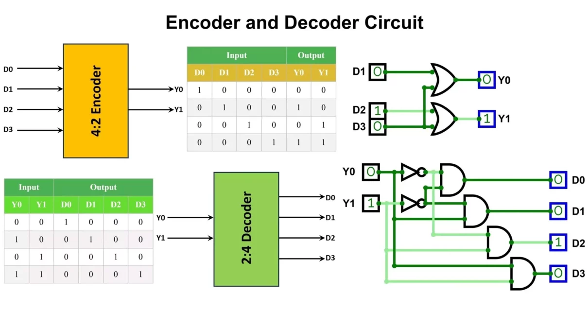
While they may seem like two sides of the same coin, encoders and decoders serve opposite but equally crucial roles. In this article, we’ll learn about difference between encoder and decoder with their types, pros and cons, real-world applications, and some of the most commonly used encoder and decoder ICs.
In the world of digital electronics and communication systems, encoders and decoders are the unsung heroes behind how data is represented, transmitted, and processed. From powering communication networks and computer systems to driving robotics, industrial automation, and data conversion – these circuits are everywhere.
What is an Encoder?
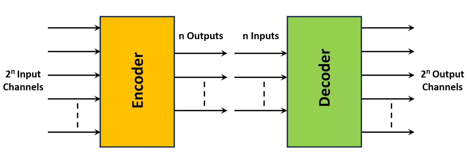
An Encoder is a combinational circuit designed to convert 2ⁿ distinct input lines into an n-bit binary code. In simpler words, it performs data compression by encoding multiple input signals into fewer output bits. Encoders are widely used in systems where input signals outnumber output data lines.
Basic Encoder Operation
If an encoder has 2ⁿ input lines, only one of the inputs is active (logic high) at a time, and the circuit produces an n-bit binary code that corresponds to the active input line.
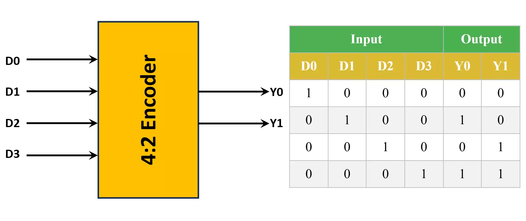
Example: A 4-to-2 encoder takes 4 input lines (D0 to D3) and produces a 2-bit binary code representing which input is active.
4:2 Encoder Circuit
A 4:2 Encoder has:
- 4 inputs:
D0, D1, D2, D3(Only one input is HIGH at a time) - 2 outputs:
Y1, Y0
Truth Table
Boolean Functions
Since only one input is active at a time:
Y1 = D2 + D3Y0 = D1 + D3
Logic Circuit
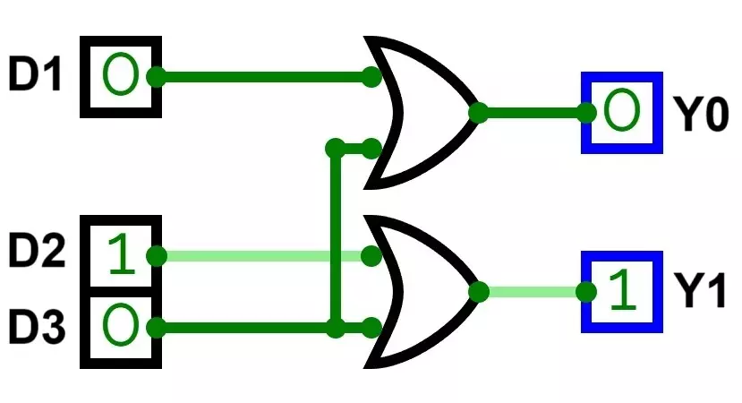
You just need two 2-input OR gates.
What is a Decoder?
A Decoder is another fundamental combinational circuit that performs the reverse function of an encoder. It takes an n-bit binary input and generates its equivalent 2ⁿ output lines. The output line corresponding to the binary input code is activated (logic high), and all others remain inactive.
Basic Decoder Operation
For a decoder with n input lines, it generates 2ⁿ unique output lines. The combination of inputs selects which specific output will be active.
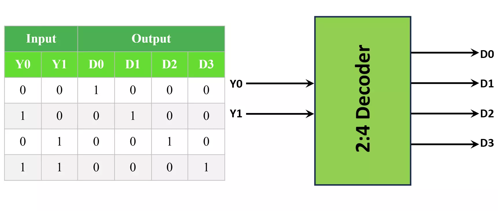
Example: A 2-to-4 decoder takes a 2-bit input and generates 4 outputs (D0 to D3), with only one output activated depending on the binary input.
2:4 Decoder Circuit
A 2:4 Decoder has:
- 2 inputs:
Y1, Y0 - 4 outputs:
D0, D1, D2, D3
Truth Table
Boolean Functions
D0 = Y1' · Y0'D1 = Y1' · Y0D2 = Y1 · Y0'D3 = Y1 · Y0
(' means NOT)
Logic Circuit
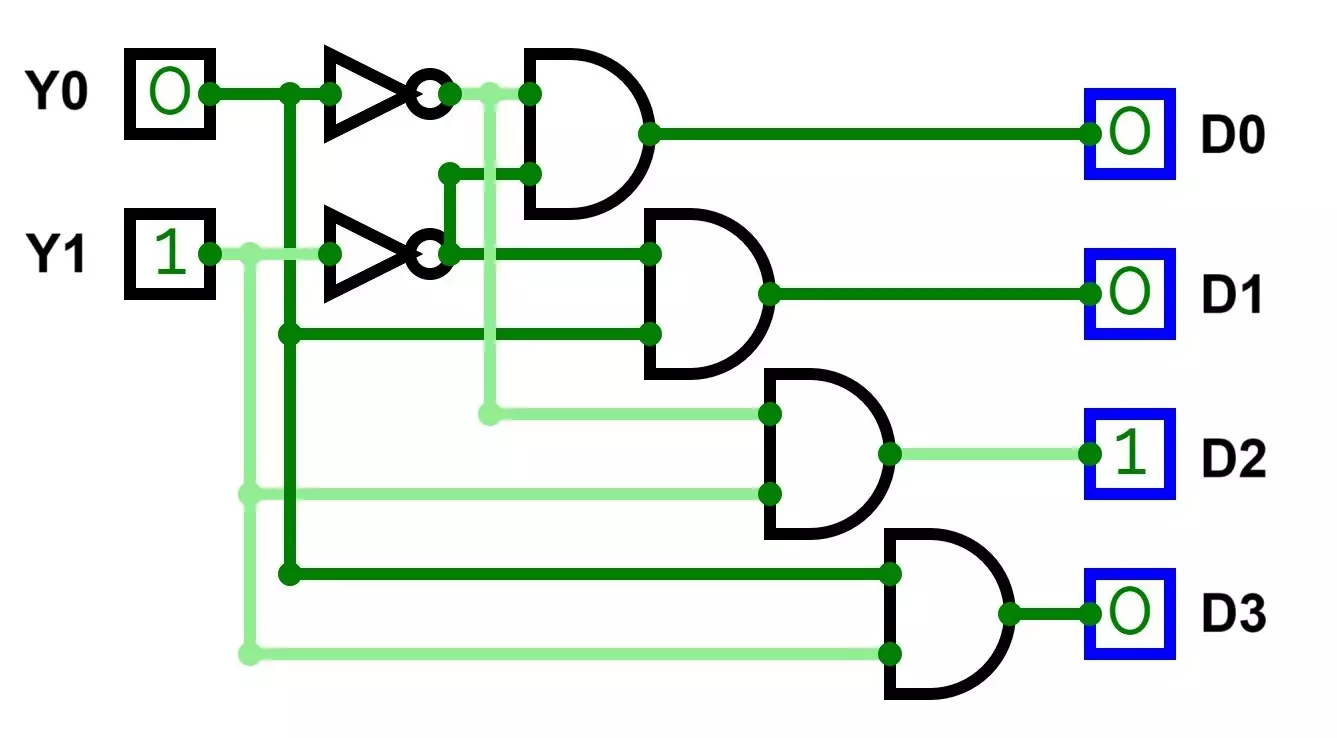
You will need:
Types of Encoders and Decoders
Types of Encoders
Priority Encoder
It assigns priority to the inputs when more than one input is active simultaneously, outputting the highest-priority active input. Example: 4-to-2 priority encoder.
Decimal to BCD Encoder
Converts decimal inputs into Binary-Coded Decimal (BCD) outputs.
Keyboard Encoder
Used in computer keyboards to encode the pressed key into its respective binary code.
Rotary Encoder
Converts the angular position of a rotating shaft into a digital code, commonly used in robotics and automation.
Optical Encoder
Utilized for motion sensing and position feedback in robotics and CNC machinery. It uses light sensors and patterns to detect movement.
Magnetic Encoder
Uses magnetic fields and sensors to detect shaft rotation, often used in harsh environments where optical encoders might fail.
Types of Decoders
Binary to Decimal Decoder
Converts binary numbers into their equivalent decimal outputs.
BCD to Seven-Segment Decoder
Takes a BCD input and drives a seven-segment display, widely used in digital clocks, counters, and calculators.
Demultiplexer (DEMUX)
A special decoder that acts as a switch, routing a single input to one of many outputs.
Address Decoder
Used in microprocessors and memory systems to select specific memory locations.
Binary to Gray Code Decoder
Used in systems requiring error-minimized transitions such as encoders for rotary positioning.
Advantages and Disadvantages Encoder and Decoder
Advantages of Encoders
- Reduces the number of data lines required.
- Minimizes complexity and bulkiness of wiring.
- Cost-effective in data acquisition and communication systems.
- Converts physical motion into digital signals (e.g., rotary and optical encoders).
- Enhances data security in communication through encoding.
Disadvantages of Encoders
- Non-priority encoders may create errors if multiple inputs are active.
- Requires additional priority logic in complex applications.
- Mechanical encoders may degrade over time due to wear and tear.
- Susceptible to noise and interference in harsh environments.
Advantages of Decoders
- Helps in data distribution and selection.
- Plays a crucial role in memory and address decoding.
- Essential for driving display systems like seven-segment and LCDs.
- Integral part of error detection and correction mechanisms.
Disadvantages of Decoders
- Increases circuit size and complexity, especially with higher bit widths.
- More output lines increase power consumption.
- Limited scalability without cascading additional decoders.
- May require buffering in large systems to maintain signal integrity.
Common Applications of Encoders and Decoders
Applications of Encoders
- Computer keyboards (Keyboard Encoder)
- Robotics (Position, speed, and direction control)
- Elevator and conveyor belt control systems
- Data compression and secure transmission systems
- CNC machines and industrial automation
- Radar and sonar signal processing
Applications of Decoders
- Memory Address Decoding in RAM, ROM, and Cache
- Data Demultiplexing in communication systems
- Display systems (Seven-segment, dot matrix, LCD)
- Instruction decoding inside microprocessors
- Frequency selection in communication receivers
- Error detection and correction circuits
Difference Between Encoder and Decoder
Here is an in depths comparison between encoder and decoder.
| Feature | Encoder | Decoder |
|---|---|---|
| Definition | Converts multiple inputs or message signals into a binary code, often Binary Coded Decimal (BCD) | Converts binary code, often BCD, into the original message signal or multiple outputs |
| Purpose | Converts original data into a coded form for efficient transmission, storage, or processing | Converts the coded data back into its original or usable form |
| Inputs | 2ⁿ Inputs (many inputs) | n Inputs (fewer inputs) |
| Outputs | n Outputs (fewer outputs, BCD form) | 2ⁿ Outputs (many outputs, original signal) |
| Input Data | Takes the original message signal as input | Takes the encoded BCD signal as input |
| Output Data | Its output is a BCD (Binary Coded Decimal) or encoded signal | Its output is the original message signal |
| Operation Type | Data Compression / Reduction | Data Expansion / Reconstruction |
| Logic Implementation | Implemented using only OR gates | Implemented using AND and NOT gates |
| Complexity | Very simple operation | Slightly more complex operation |
| Invalid State | Has invalid input state when two or more inputs are high | No invalid input state |
| Direction | Many inputs ➤ fewer outputs | Fewer inputs ➤ many outputs |
| Installation | Installed at the transmitting end | Installed at the receiving end |
| Dependency | Independent, but paired with a matching decoder | Dependent on the encoder’s output |
| Typical Applications | Encoding data for emails, videos, messages, calls, sensor data conversion, multimedia encoding | Decoding received encoded data in microprocessors, memory addressing, data demultiplexing, display driving, multimedia playback |
Common Encoder and Decoder ICs
Encoder ICs
1. 74LS148 – 8-to-3 Line Priority Encoder
- TTL based IC
- Accepts 8 input lines and generates a 3-bit output
- Includes priority logic to handle simultaneous inputs
- Frequently used in keyboard encoders and data acquisition systems
2. CD4532 – 8-to-3 Line Priority Encoder
- CMOS technology
- Offers priority encoding and cascading capability
- Suited for both consumer and industrial electronic systems
3. HT12E – Encoder IC for RF Communication
- Encodes 12-bit data (8 address bits + 4 data bits)
- Commonly used in RF remote controls, automation, and wireless security systems
- Often paired with HT12D decoder
Decoder ICs
1. 74LS138 – 3-to-8 Line Decoder / Demultiplexer
- TTL technology
- Widely used for memory address decoding and data demultiplexing
- Enable inputs allow for cascading to expand the number of outputs
2. 74LS47 – BCD to 7-segment Decoder
- Drives common anode seven-segment LED displays
- Capable of displaying decimal numbers directly
3. CD4514 – 4-to-16 Line Decoder / Demultiplexer
- CMOS based
- Ideal for applications like data distribution, display driving, and address decoding
4. HT12D – Decoder IC for RF Communication
- Decodes 12-bit data (8 address + 4 data bits)
- Primarily used in remote control applications alongside HT12E
Conclusion
Encoders and decoders are indispensable components of modern digital systems. Encoders simplify systems by reducing the number of data lines, making them efficient for data acquisition, motion sensing, and secure communication. Decoders, on the other hand, help expand binary data into multiple meaningful outputs essential for memory systems, displays, and data routing. Both circuits are vital for enabling compact, scalable, and efficient designs.
When working on projects involving data conversion, address selection, display units, or communication systems, selecting the appropriate type of encoder or decoder is essential. A thorough understanding of the differences between encoder and decoder, their functionality, types, limitations, and available ICs ensure robust and optimized designs for a variety of modern applications.
Types of Logic Gates with Symbol, Truth Table and IC Numbers
