Discover the key differences between Edge Triggering and Level Triggering in digital circuits. This article explains how each triggering method works, their advantages, disadvantages, applications, and how to use them in flip-flops and clocked circuits. Gain a clear understanding of these fundamental concepts in digital electronics with examples.
What is a Sequential Circuit?
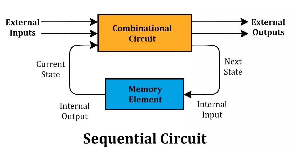
A sequential circuit is a digital circuit in which the output is determined not only by the present inputs but also by past inputs and previous states. Unlike combinational circuits, which provide an output purely based on current inputs, sequential circuits use memory elements (such as flip-flops or latches) to store previous states. This memory capability allows them to perform tasks that require state retention, such as counters, registers, and finite state machines.
Types of Sequential Circuits
Sequential circuits are categorized into two main types:
- Synchronous Sequential Circuits – These circuits rely on a clock signal to synchronize state changes, ensuring predictable timing and operation.
- Asynchronous Sequential Circuits – These circuits operate independently of a clock signal, changing states based on input variations, making them faster but more prone to timing hazards.
What is a Clock Pulse?
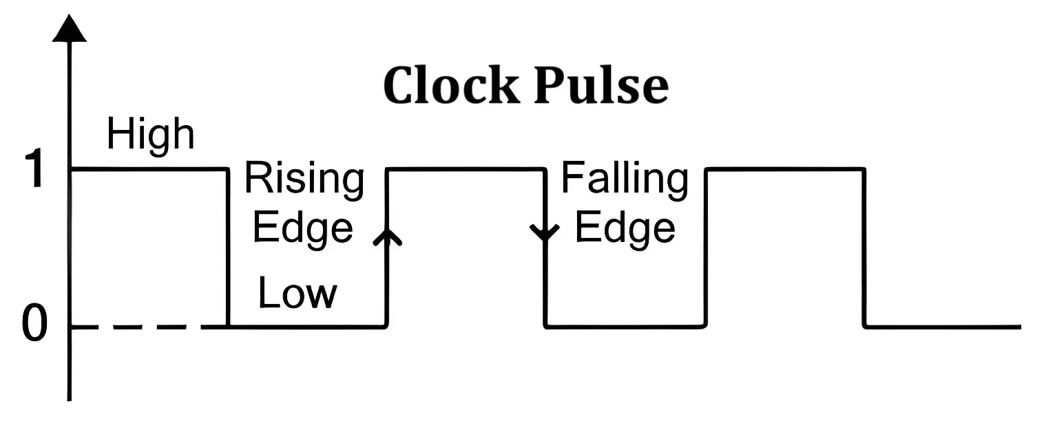
A clock pulse is a periodic oscillating signal used to control the timing of sequential circuits. It alternates between high (1) and low (0) states at a fixed rate, ensuring that flip-flops and registers update their values at precise intervals.
Properties of a Clock Signal:
- Period (T) – The duration of one complete cycle of the clock signal.
- Frequency (f) – The number of cycles per second, measured in Hertz (Hz).
- Duty Cycle – The percentage of time the signal remains HIGH during one cycle.
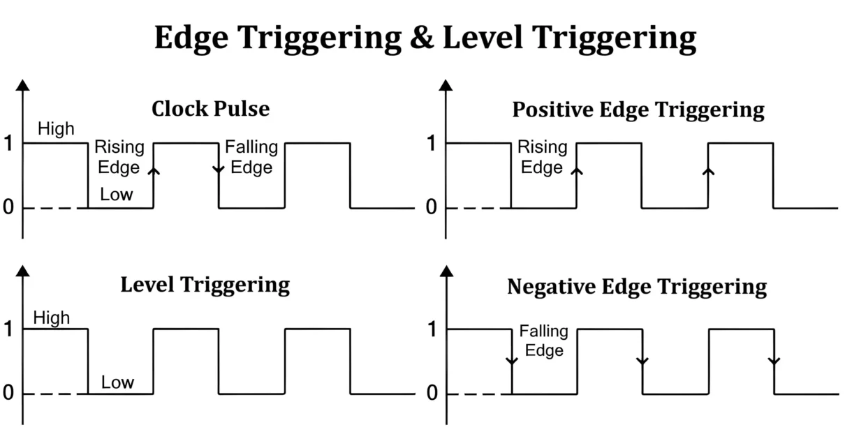
- Rising Edge (Positive Edge) – The transition of the clock signal from LOW to HIGH (0 → 1).
- Falling Edge (Negative Edge) – The transition of the clock signal from HIGH to LOW (1 → 0).
Edge Triggering
Edge triggering is a mechanism where a circuit responds only at the transition points (edges) of a clock pulse, either at the rising edge or the falling edge.
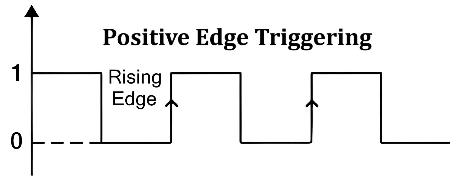
1. Positive Edge Triggering
A circuit is said to be positively edge-triggered if it responds only when the clock transitions from LOW to HIGH (0 → 1). Flip-flops that use this method are represented by a triangle (—►) symbol on the clock input.
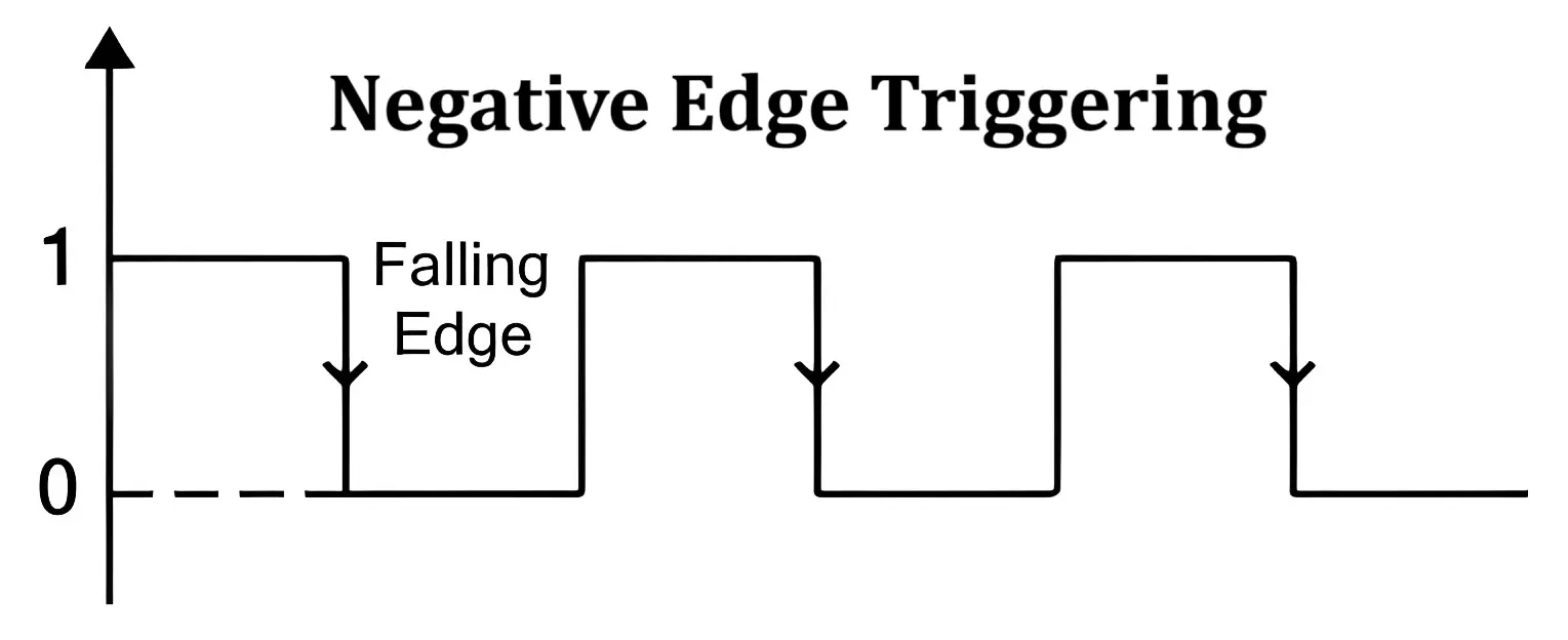
2. Negative Edge Triggering
Negative edge triggering occurs when a circuit responds exclusively to the falling edge of the clock pulse (1 → 0). Flip-flops that utilize this method are represented by a triangle and a small circle (—o►) on the clock input.
Level Triggering
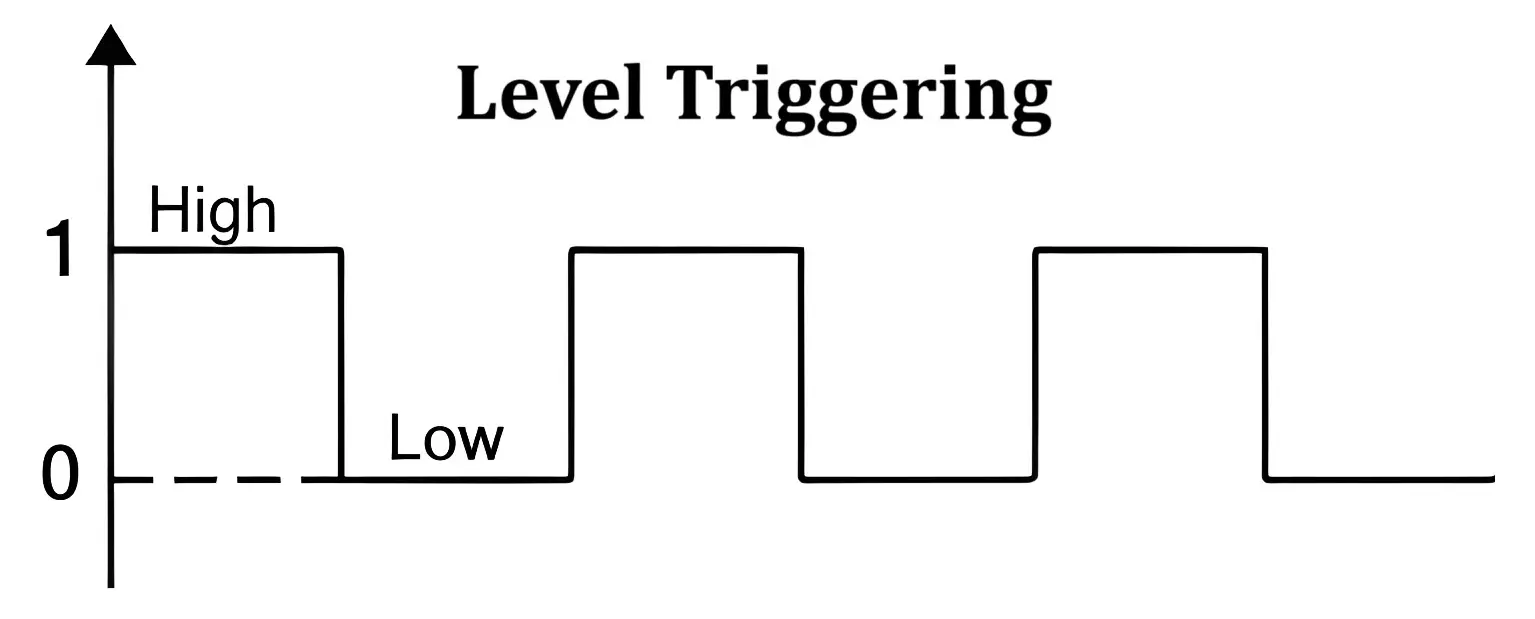
Level triggering, unlike edge triggering, allows the circuit to respond throughout the duration when the clock signal is at a particular logic level (HIGH or LOW).
1. Positive Level Triggering
Positive level triggering occurs when the circuit remains active as long as the clock signal is HIGH (logic 1). This type of triggering is represented using a straight line (—) with a HIGH-level indication.
2. Negative Level Triggering
Negative level triggering occurs when the circuit remains active as long as the clock signal is LOW (logic 0). This is denoted using a straight line (—) with a LOW-level indication.
How Do Edge and Level Triggering Work?
- Edge triggering ensures that a circuit changes state only at a specific moment (either the rising or falling edge of the clock pulse). This mechanism helps prevent multiple activations during a single clock cycle.
- Level triggering, in contrast, allows the circuit to continuously respond while the clock signal remains at a particular logic level (HIGH or LOW). This can lead to unwanted transitions if not carefully managed.
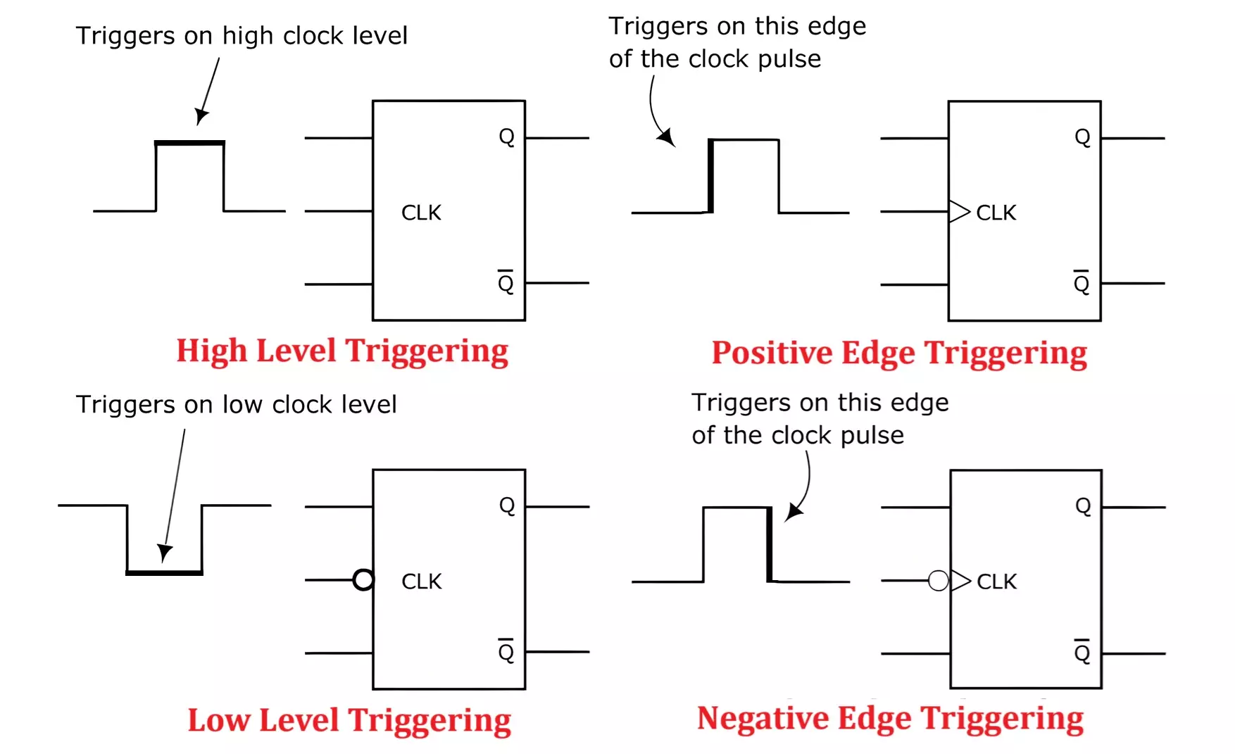
Symbols for Edge and Level Triggering
- Positive Edge Triggering (—►) – Active only on the rising edge of the clock.
- Negative Edge Triggering (—o►) – Active only on the falling edge of the clock.
- Positive Level Triggering (—) – Active when the clock signal is HIGH.
- Negative Level Triggering (—o) – Active when the clock signal is LOW.
Edge Triggering vs Level Triggering Difference
| Feature | Edge Triggering | Level Triggering |
|---|---|---|
| Definition | A circuit activates only when a change occurs at the clock edge. | A circuit remains active as long as the clock is at a specific logic level. |
| Activation | Responds only to clock transitions (rising or falling edge). | Stays active for the entire duration of the HIGH or LOW clock state. |
| Sampling | Takes input values at the exact moment of the clock transition. | Continuously samples input signals while the clock is at a given level. |
| Stability | Reduces the risk of unintended activations and glitches. | More prone to glitches due to continuous signal monitoring. |
| Circuit Application | Primarily used in synchronous sequential circuits. | More common in asynchronous sequential circuits. |
| Common Uses | Ideal for applications requiring precise timing, such as flip-flops, counters, and timers. | Suitable for continuous monitoring applications like latches, sensors, and alarm systems. |
Advantages and Disadvantages
Advantages of Edge Triggering
- Eliminates the risk of multiple activations within a single clock cycle.
- Provides better control and synchronization in sequential circuits.
- Less susceptible to glitches and metastability issues.
- Preferred for high-speed and precise-timing applications.
Disadvantages of Edge Triggering
- More complex to design compared to level-triggered circuits.
- Requires precise clock signals to function accurately.
Advantages of Level Triggering
- Simpler circuit design compared to edge-triggered mechanisms.
- Allows for continuous monitoring of input signals.
- Suitable for applications where state retention is necessary.
Disadvantages of Level Triggering
- Prone to glitches due to continuous sensitivity to input changes.
- Can lead to multiple unwanted activations during a single clock cycle.
Practical Applications
Edge Triggered Circuits
- Flip-Flops – Used in registers and memory storage (D, T, and JK flip-flops).
- Counters – Synchronous binary and decade counters.
- Timers – Digital timer circuits for precise time-based operations.
- Microprocessors – Utilized in CPU clocking mechanisms for instruction execution.
Level Triggered Circuits
- Latches – SR and D latches for simple data storage.
- Sensors and Alarms – Motion detectors and fire alarm circuits that require continuous monitoring.
- Asynchronous State Machines – Control circuits that do not require clock synchronization.
Conclusion
Understanding edge and level triggering is essential for designing reliable sequential circuits. Edge-triggered circuits provide better control and timing stability, making them the preferred choice for counters, registers, and microprocessors. Level-triggered circuits, while simpler, require careful design to avoid unintended transitions. The choice between edge and level triggering ultimately depends on the specific application and its requirements for precision and responsiveness.
Types of Logic Gates with Symbol, Truth Table and IC Numbers
Universal NOR Gate Truth Table, Logic Circuit & IC 7402 PIN Diagram
