The Universal DC-DC Buck & Boost Converter Circuit with UC3843 is a versatile circuit that can be used to either boost or buck a DC voltage, depending on the specific configuration. The UC3843 is a popular PWM (Pulse Width Modulation) controller IC used for these types of converters because of its high performance and ease of use. Here’s a general overview of how it works and what you might need to consider:
Understanding the DC-DC Voltage Converter Circuit:
Let’s work on creating a versatile, portable power source capable of handling various tasks. This can charge portable gadgets, such as smartphones, laptops, power DC soldering irons, cameras, and other devices. To achieve this, you needed a power supply that could deliver different voltages, ranging from 5 to 24 volts. The battery pack we generally get is around 12 volts, so we need a converter that could both increase and decrease this voltage as needed.
This project is a compact yet powerful single-cycle voltage converter. Unlike traditional converters that either step up or step down the input voltage, this one can do both. You might wonder how this is possible let’s dive in.
Key Components and Circuit Design:
UC3843 IC:
Function: It controls the switching frequency and duty cycle to regulate the output voltage.
Features: The IC includes features like undervoltage lockout (UVLO), current limiting, and an error amplifier for feedback.
Inductor:
Purpose: Stores energy when the switch is on and releases it when the switch is off, which is crucial for both step-up and step-down operations. Here we have used High Current Toroidal Choke inductor HCTC.
Switching MOSFET:
Purpose: Acts as the switch controlled by the UC3843 to connect and disconnect the inductor from the input voltage.
Diode:
Purpose: Provides a path for the inductor current when the MOSFET is off. The type of diode (Schottky, fast recovery) is chosen based on the switching speed and efficiency requirements.
Capacitors:
Input Capacitor: Filters out input noise and stabilizes the input voltage.
Output Capacitor: Filters the output to provide a smooth DC voltage.
Feedback Network:
Purpose: Monitors the output voltage and provides feedback to the UC3843 to adjust the duty cycle for voltage regulation.
Step-Up (Boost) Configuration:
- In this mode, the converter increases the input voltage to a higher output voltage.
- The inductor is charged when the MOSFET is on, and the energy stored in the inductor is transferred to the output when the MOSFET is off, along with the input voltage.
Step-Down (Buck) Configuration:
- In this mode, the converter reduces the input voltage to a lower output voltage.
- The MOSFET switches on and off rapidly, transferring energy to the inductor, which then supplies a lower voltage to the output.
Design Considerations:
- Switching Frequency: The UC3843 can operate at frequencies up to 500 kHz, allowing for smaller passive components but also requiring careful layout to avoid noise.
- Efficiency: Both configurations aim for high efficiency, but it’s crucial to select components that match the load requirements and minimize losses.
- Thermal Management: Depending on the load and efficiency, heat dissipation might become significant, so proper cooling (heat sinks, PCB design) is necessary.

Building the Versatile DC-DC Converter Circuit:
The circuit design was crucial. I focused on making the board compact while meeting my specific needs. If you decide to replicate this project, I suggest assembling several converters at once, as they are multi-purpose and can be used in many applications, such as charging gadgets and powering LEDs.
Output Current and Circuit Components:
The power supply delivers an output current of up to 3 amperes, which suffices for my needs due to the small capacity of the storage capacitors. However, the circuit is designed to provide up to 5 amperes, making it highly versatile. The output current depends on the capacitance of the capacitors, the choke, the field-effect transistor, and the diode rectifier used in the circuit.

The circuit is a single-ended converter based on the PWM controller UC3843. If given relatively higher voltage add a 12-volt linear regulator to the board for smooth operation of the PWM chip. While this regulator isn’t shown on the circuit diagram, it’s essential for stable performance.

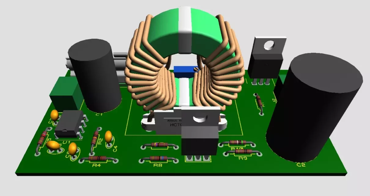
Assembling the Converter:
When assembling, pay attention to the jumpers on the board—two of them should have a diameter of at least 1 millimeter. The choke, a crucial component, is wound on a yellow and white ring made of powdered iron, commonly used in computer power supplies output filters. The choke I used has two equivalent windings, each with a 1.2-millimeter wire, but I recommend using a slightly larger diameter (1.5 to 2 millimeters) for better performance. The windings should be wound simultaneously and in the same direction.
Power Transistor and Rectifier:
The power transistor can be any low-voltage N-channel field-effect transistor with a current rating of 30 amperes. I used the IRFZ44 transistor. The output rectifier is a dual diode in a TO-220 package. It’s advisable to use Schottky diodes (MBR10100CT) due to their low voltage drop, which minimizes losses. These diodes are also commonly found in computer power supplies, used as output rectifiers.
Feedback and Protection Mechanisms:
The converter is stabilized and features feedback. The output voltage is set by resistor R3, which can be replaced with a conventional variable resistor for easier adjustment. The converter also includes short-circuit protection, using a low-resistance shunt resistor (R10) as a current sensor. If protection isn’t needed, this part can be excluded. Additionally, a 10-ampere fuse provides further protection.
Final Assembly and Testing:

The capacitors used in the circuit should have a low internal resistance. The power elements, including the transistor and rectifier, are mounted on an aluminum plate. Don’t forget to isolate these elements from the heat sink using heat-conducting insulating pads, and thermal paste.
Thanks to the PWM controller, this converter boasts high efficiency. The no-load current varies between 20 to 40 milliamperes, depending on the supply voltage. Testing the circuit revealed a maximum output voltage of about 25 volts when applying 12 volts to the input. The minimum voltage is around 5 volts, making it suitable for charging smartphones. The stabilization worked flawlessly, maintaining the output voltage even when the input voltage varied.

Despite its compact size, this converter can deliver an output current of 2.5 to 3 amperes with minimal voltage drop. With proper adjustments, currents of 5 amperes or more are achievable. It’s important to reinforce the power tracks on the PCB with solder, as they will carry significant currents.
Please watch this video for complete understanding.
Applications of DC-DC Converter Circuit:
DC-DC converters are widely used in enhancing the efficiency and reliability of electronic systems across different industries. Here are some common applications DC-DC converters circuits:
1. Power Supply Regulation
- Voltage Regulation: DC-DC converters are used to step up or step down voltage levels to provide a stable and regulated output voltage for electronic devices.
- Battery-Powered Devices: Portable devices like smartphones, laptops, and tablets use DC-DC converters to efficiently manage power from batteries, ensuring longer battery life.
2. Automotive Applications
- Electric Vehicles (EVs): In electric vehicles, DC-DC converters manage power distribution from the high-voltage battery to low-voltage systems such as lighting, infotainment, and control units.
- Battery Management Systems (BMS): DC-DC converters help maintain the correct voltage levels in different parts of the vehicle’s electrical system.
3. Renewable Energy Systems
- Solar Power Systems: DC-DC converters are used in solar inverters to convert the varying DC output from solar panels to a stable DC voltage, which can then be converted to AC for grid connection.
- Wind Turbines: They are used to regulate the voltage generated by wind turbines before it is fed into the grid or stored in batteries.
4. Telecommunications
- Base Stations: DC-DC converters provide stable power to base station equipment, ensuring consistent communication signals.
- Networking Equipment: Routers, switches, and other networking devices use DC-DC converters to maintain the correct operating voltage.
5. Industrial Applications
- Motor Drives: DC-DC converters are used in controlling and regulating the speed of DC motors in industrial machines.
- Robotics: They are used in robots to manage power distribution between different subsystems, ensuring efficient operation.
6. Aerospace and Defense
- Satellite Power Systems: Satellites use DC-DC converters to manage power from solar panels, ensuring a stable power supply to onboard systems.
- Military Equipment: DC-DC converters provide reliable power in harsh environments, crucial for the operation of military communication and navigation systems.
7. Consumer Electronics
- Portable Chargers: DC-DC converters in power banks and chargers efficiently convert battery voltage to the required output voltage for charging devices.
- Wearable Devices: Smartwatches and fitness trackers use DC-DC converters to maximize battery life while maintaining performance.
8. Healthcare Equipment
- Medical Devices: Portable medical devices like insulin pumps and wearable monitors use DC-DC converters for efficient power management, ensuring reliable operation.
9. Data Centers
- Server Power Supplies: DC-DC converters in data centers provide efficient power distribution, reducing energy consumption and heat generation.
- Uninterruptible Power Supplies (UPS): They manage power conversion in UPS systems, ensuring stable operation during power outages.
Conclusion:
This converter, paired battery, will enable you to create a standalone power supply with adjustable output voltage. A valuable tool for many power requirements.
All the necessary links, including the project schematic and the components for assembling this converter, are given on Download Button. Please rate this article, leave feedback, and visit our electronics cannel & page.
Switch Mode Power Supply SMPS Block Diagram & Working

Good day, what software did you use to simulate?
Proteus
premium version? or what is the version of your proteus because my proteus doesn’t have that kind of IC
Search properly you will get it.
Hello, thank you very much for your efforts. Could you please provide some explanations about the inductor? I think the specifications of the inductor are not mentioned anywhere in the text. I would really appreciate your kindness in answering my question.
Wishing you continued success.
it’s a 1.5mm to 2mm 10 turn copper wire.
Size of Core is 23.3mm in widths and 13.6mm in height.
You can see in the video.