
A boost converter circuit is a DC-DC power converter that steps up voltage from its input to its output while stepping down current. It’s widely used in applications where a higher output voltage is required from a lower input voltage, such as in battery-operated devices. One of the simplest ways to design a boost converter circuit is by using the versatile 555 timer IC. The 555 timer can be configured as an astable multivibrator to generate a PWM (Pulse Width Modulation) signal, which drives a switching transistor in the boost converter circuit.
Working Principle of a Boost Converter:
A boost converter operates on the principle of energy storage in an inductor during the ON period of a switching transistor and energy transfer to the load during the OFF period. The basic components of a boost converter include:
- Inductor (L): Stores energy when the switch is ON and releases it when the switch is OFF.
- Diode (D): Ensures that current flows in one direction from the inductor to the output.
- Switch (typically a MOSFET): Alternates between ON and OFF states to control the charging and discharging of the inductor.
- Capacitor (C): Smooths the output voltage by filtering out the high-frequency components.
- Load: The device or circuit that requires the boosted voltage.
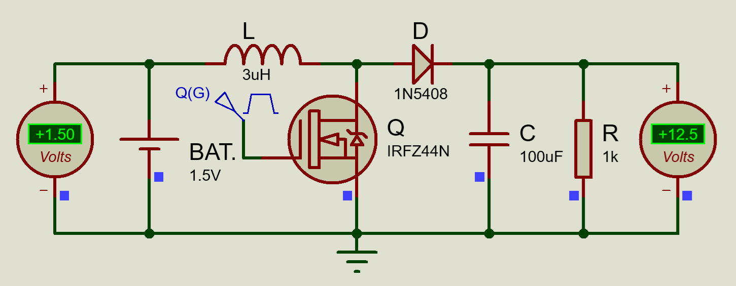
When the switch is ON, the inductor stores energy by building up a magnetic field. When the switch is turned OFF, the energy stored in the inductor is released through the diode to the load, and the voltage across the load increases. By adjusting the duty cycle of the PWM signal driving the switch, the output voltage can be controlled.
Simple DC – DC Boost Converter Circuit:
555 Timer as a PWM Generator:
The 555 timer is an IC that can be configured in various modes. For the boost converter, it’s used in astable mode to generate a PWM signal. In astable mode, the 555 timer continuously oscillates between high and low states, producing a square wave output.
Components Required:
- 555 Timer IC
- Inductor (value depends on the desired output voltage and current)
- Diode (fast recovery diode like 1N5819)
- N-channel MOSFET or NPN transistor (e.g., IRF540N, IRFZ44N or 2N2222)
- Capacitor (electrolytic capacitor for smoothing)
- Resistors and capacitors for setting the frequency and duty cycle of the 555 timer
- Power supply (typically a DC voltage source)
- Load (e.g., an LED, motor, or any other device)
Circuit Diagram:
Explanation of Circuit Operation:
555 Timer Configuration:
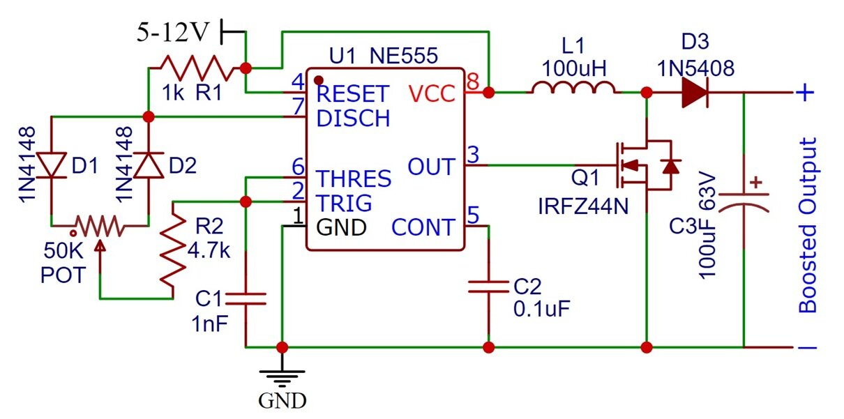
The 555 timer is configured in astable mode. The frequency of the PWM signal is determined by the resistors R1, R2, and the capacitor C1. The duty cycle of the PWM signal, which determines how long the switch (MOSFET or transistor) stays ON and OFF, is crucial for controlling the output voltage.
Inductor and Switch:
The inductor L stores energy when the transistor is ON. During the OFF period of the transistor, the inductor releases its stored energy, which is directed through the diode D1 to the output capacitor C3 and the load.
Diode and Capacitor:
The diode D1 ensures that the current flows in the correct direction, preventing backflow of current. The output capacitor C3 smooths the voltage to ensure a steady DC output.
Load:
The load connected to the output of the boost converter receives the boosted voltage. The output voltage depends on the duty cycle of the PWM signal and the input voltage.
Calculations and Design Considerations:
Choosing the Inductor:
The value of the inductor is critical in determining the efficiency and performance of the boost converter. A typical value might range from 10 µH to 100 µH depending on the input voltage, output voltage, and load current.
Duty Cycle (D):
- Duty Cycle (%): The duty cycle indicates the percentage of time the output is high during each cycle. It is calculated as:
(T_high / T) × 100– T_high is the time the output is high.
– T is the total time period.
- Time Period (T): The time period is the duration of one complete cycle of the waveform:
1 / F– This represents the time taken for one complete high and low cycle.
- Time High (Th): The time the output remains high is:
T_high =
0.693 × (R1 + R2) × C1 - Time Low (Tl): The time the output remains low is:
T_low =
0.693 × R2 × C1
Frequency:
The frequency of the PWM signal should be high enough to allow efficient energy transfer but not too high to avoid excessive switching losses. A typical frequency range can be 50 kHz and 100 kHz.
-
F =
1.44 / ((R1 + 2R2) × C1)–
R1andR2are the resistors connected to the 555 timer.–
C1is the capacitor connected to the timer.
Capacitor Selection:
The output capacitor should have a low ESR (Equivalent Series Resistance) to minimize voltage ripple. The capacitance value should be large enough to smooth out the high-frequency components of the output voltage.
Advantages of Using 555 Timer in Boost Converter:
- Simplicity: The 555 timer is a widely available, easy-to-use IC, making it ideal for simple boost converter circuits.
- Adjustability: By changing the values of the resistors and capacitors, the output voltage and frequency can be easily adjusted.
- Cost-effective: The 555 timer is inexpensive, making the overall cost of the boost converter circuit low.
Limitations:
- Efficiency: While the 555 timer-based boost converter is simple, it may not be as efficient as dedicated boost converter ICs, especially at higher power levels.
- Limited Control: The 555 timer offers basic PWM control but lacks the advanced features of modern boost converter ICs, such as soft start, overcurrent protection, and thermal shutdown.
- Component Selection: The choice of components, especially the inductor and diode, is critical to the performance of the circuit. Improper selection can lead to poor efficiency and performance.
Applications of Boost Converter Circuit:
Boost converters have a wide range of applications due to their ability to step up voltage while managing power efficiency. Here are some of the key applications:
1. Battery-Powered Devices
- Portable Electronics: Boost converters are commonly used in portable devices like smartphones, tablets, and wearable devices to step up the voltage from a battery to the required operating voltage of the device.
- Flashlights: Many LED flashlights use boost converters to drive high-brightness LEDs from lower voltage batteries, providing consistent light output.
2. Solar Power Systems
- Solar Chargers: Boost converters are employed in solar chargers to increase the voltage from solar panels to the level required to charge batteries or power electronic devices.
- Grid-Tied Inverters: In solar power systems, boost converters are used to raise the voltage from the solar panels to match the voltage required by the grid or other components of the system.
3. Electric Vehicles (EVs)
- Battery Management Systems: In electric vehicles, boost converters are used to step up the battery voltage to power various components like the motor, lights, and electronic control units.
- Regenerative Braking: During regenerative braking, boost converters help in converting the kinetic energy back into electrical energy, which is then stored in the battery.
4. Power Supply Circuits
- Uninterruptible Power Supplies (UPS): Boost converters are used in UPS systems to step up the battery voltage to the required AC voltage levels during power outages.
- DC-DC Converters: Boost converters are an integral part of DC-DC converter circuits. They are used in many power supply designs to provide stable and regulated output voltages.
5. Automotive Applications
- Car Audio Systems: High-power car audio systems often use boost converters to provide the necessary voltage levels for amplifiers and other audio components.
- LED Headlights: Boost converters are used in automotive lighting to power high-brightness LEDs from the car’s lower voltage electrical system.
6. Telecommunication Equipment
- Base Stations: In telecommunications, boost converters are used to ensure stable voltage levels for base station equipment, especially in remote or off-grid locations.
- Power Amplifiers: Boost converters provide the necessary high voltage for RF power amplifiers used in communication devices and transmitters.
7. Medical Devices
- Portable Medical Equipment: Boost converters are used in portable medical devices such as blood glucose meters, portable ECG machines, and handheld diagnostic tools to step up battery voltage to the required operating levels.
- Defibrillators: In defibrillators, boost converters are used to generate the high-voltage pulses needed to deliver a shock to the patient’s heart.
8. Industrial Applications
- Robotics: In robotics, boost converters are used to power motors and control systems, ensuring that the voltage levels are sufficient to drive actuators and sensors.
- Instrumentation: Boost converters are used in industrial instrumentation to provide the necessary voltage levels for sensors and transducers.
9. Energy Harvesting
- Low-Power Wireless Sensors: Boost converters are employed in energy harvesting systems to step up low voltage generated from energy sources like thermoelectric generators, piezoelectric devices, or small solar cells to power wireless sensors.
- Wearable Technology: In wearable devices that harvest energy from body heat or movement, boost converters step up the harvested voltage to a usable level for powering the device.
10. LED Drivers
- LED Backlighting: Boost converters are used in LED backlighting for displays. They ensure that the LEDs receive a consistent and sufficient voltage for uniform brightness.
- Street Lighting: In street lighting systems, especially solar-powered ones, boost converters are used to step up the voltage to drive high-power LEDs efficiently.
11. Consumer Electronics
- Power Banks: Boost converters are used in power banks to step up the battery voltage to the USB output voltage (typically 5V) required to charge devices.
- E-Readers: E-readers and other small electronic devices often use boost converters to manage power efficiently, extending battery life.
12. Aerospace and Defense
- Satellite Systems: In satellites, boost converters are used to regulate voltage levels for various subsystems, ensuring reliable operation in space environments.
- Military Radios: Boost converters provide the necessary voltage levels for communication equipment used in defense applications, where consistent performance is critical.
Conclusion:
A boost converter circuit using a 555 timer is a practical and straightforward way to step up voltage in low-power applications. By leveraging the 555 timer’s ability to generate a PWM signal, the boost converter can be designed with minimal components and at a low cost. Although it may not offer the highest efficiency, it’s an excellent educational project for understanding the basics of boost converters and PWM control.
This circuit is ideal for hobbyists, students, and engineers looking to build a simple DC-DC converter or experimenting with power electronics concepts.
Boost converters are essential components in many modern electronic systems, providing efficient voltage conversion to meet the requirements of various applications. Whether in consumer electronics, renewable energy systems, or industrial applications, boost converters play a crucial role in ensuring that devices receive the correct voltage while optimizing power efficiency.

Why are D1 and D2 shown as zener diodes. Are they or they not zeners?
They are high-speed switching diodes, thanks for pointing