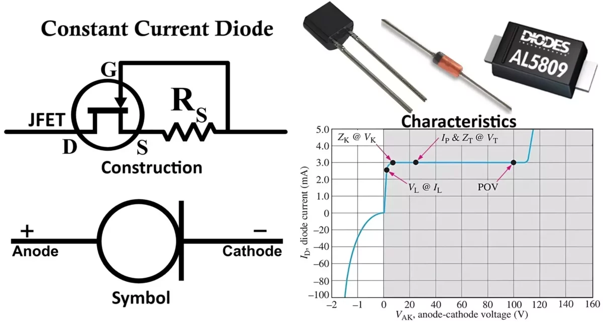
Constant Current Diode (CCD) (also known as Current Regulator Diodes, or simply CRDs) are unique semiconductor devices designed to maintain a constant current over a wide range of voltages. They are extremely useful in circuits where a stable and predictable current is crucial, regardless of voltage variations.
In this article, we will cover the Symbol, Construction, Working Principle, VI Characteristics, Advantages, Disadvantages, and Applications of Constant Current Diodes in a detailed and easy-to-understand manner.
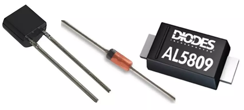
The AL5809 is a Constant Current LED Driver IC. If you need to control higher currents (15mA to 150mA), it is a good choice because the current output of the other two diodes (J501 and 1N5283) is relatively low.
Symbol of Constant Current Diode
The symbol of a Constant Current Diode does not resemble a conventional diode.
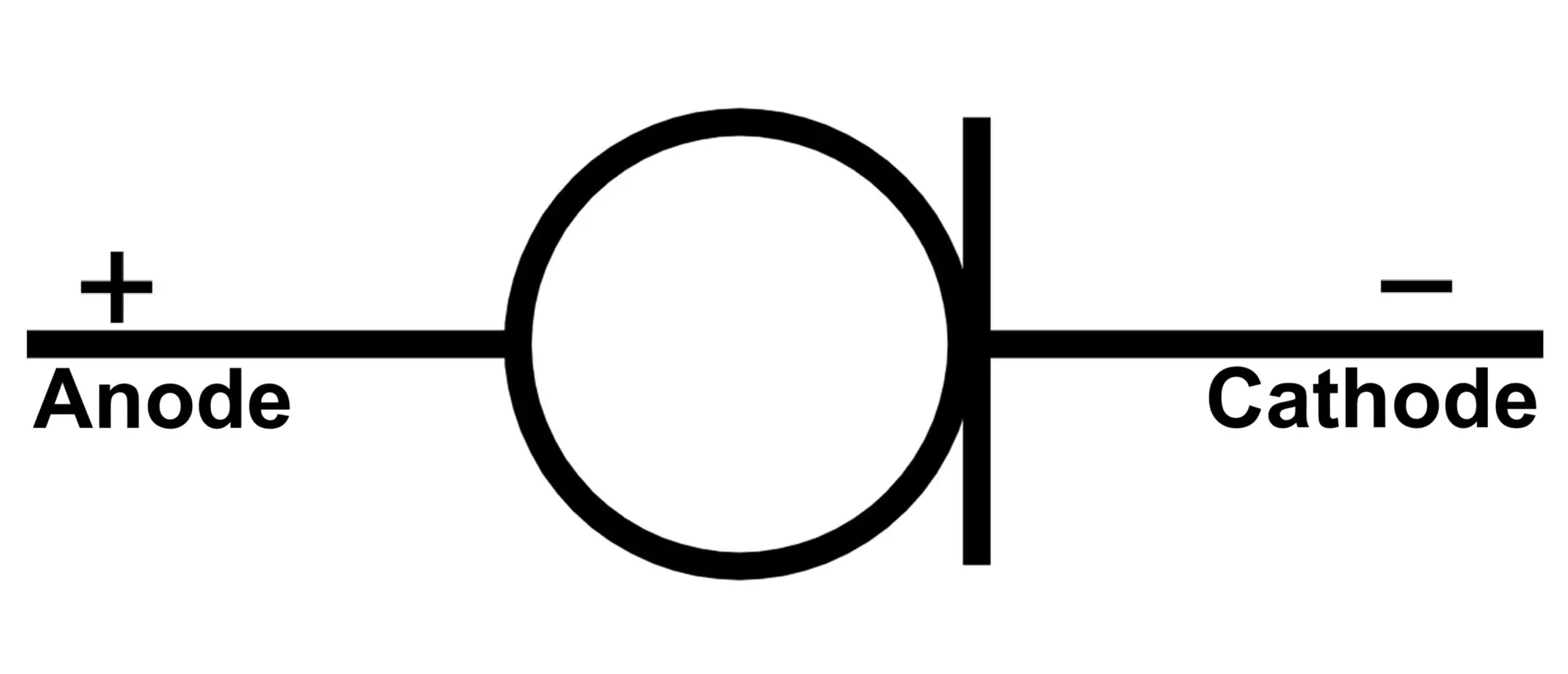
- The vertical bar line represents cathode of diode.
- Circle as current source emphasizes that current remains constant for a wide voltage range.
- Some manufacturers also depict it as a diode with a small resistor alongside it.
Note: A CCD may also be labeled as “CRD” in schematics, standing for Current Regulating Diode.
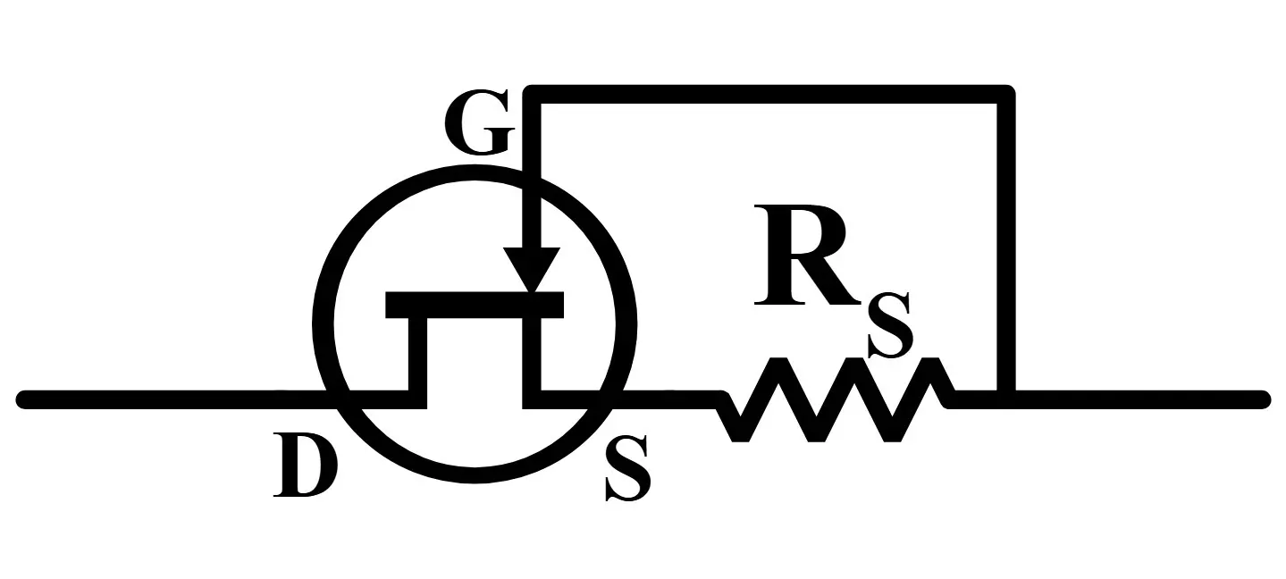
Construction of Current Regulator Diodes
The construction of a CCD is relatively simple but clever. It is essentially a Junction Field Effect Transistor (JFET) configured to work in its current-limiting region.
Key construction elements:
- JFET Structure: A semiconductor channel (n-type or p-type) with a gate terminal shorted to the source terminal.
- 2-Terminal Device: Since the gate and source are connected internally, only two terminals (anode and cathode) are exposed.
- Biasing: The device is self-biased by the voltage across it, automatically maintaining a fixed current.
Physical Layout:
- A silicon chip containing the JFET structure.
- Encapsulated in a small diode-like casing (glass or epoxy).
- Often packaged similarly to small-signal diodes (e.g., DO-35, SOD-80 packages).
Working Principle of Constant Current Diode
The working of a CCD is based on the saturation characteristics of a JFET.
- At Low Voltages:
- When the voltage across the diode is small, the device acts like a low-resistance path.
- Current increases linearly with voltage (Ohm’s Law region).
- At Moderate Voltages:
- As voltage rises, the JFET channel starts pinching off.
- Beyond a certain voltage (called the pinch-off voltage), the current saturates.
- Now, current becomes constant despite further increases in voltage.
- At High Voltages:
- If the voltage becomes too high, breakdown occurs, damaging the diode.
Thus, over a wide voltage range, the CCD maintains a fixed current (called the regulation current, denoted as Ip).
Key Points:
- Current remains constant despite fluctuations in supply voltage.
- Behavior is similar to an ideal current source within operational limits.
- The regulation current is determined by the device design (channel doping, geometry).
VI Characteristics of Constant Current Diode
The Voltage-Current (VI) characteristics of a CCD can be divided into three regions:
| Region | Description | Behavior |
|---|---|---|
| Ohmic Region | Low voltages | Acts like a resistor, current increases with voltage |
| Constant Current Region | Moderate voltages | Current stays constant despite voltage changes |
| Breakdown Region | Very high voltages | Device breaks down; destructive |
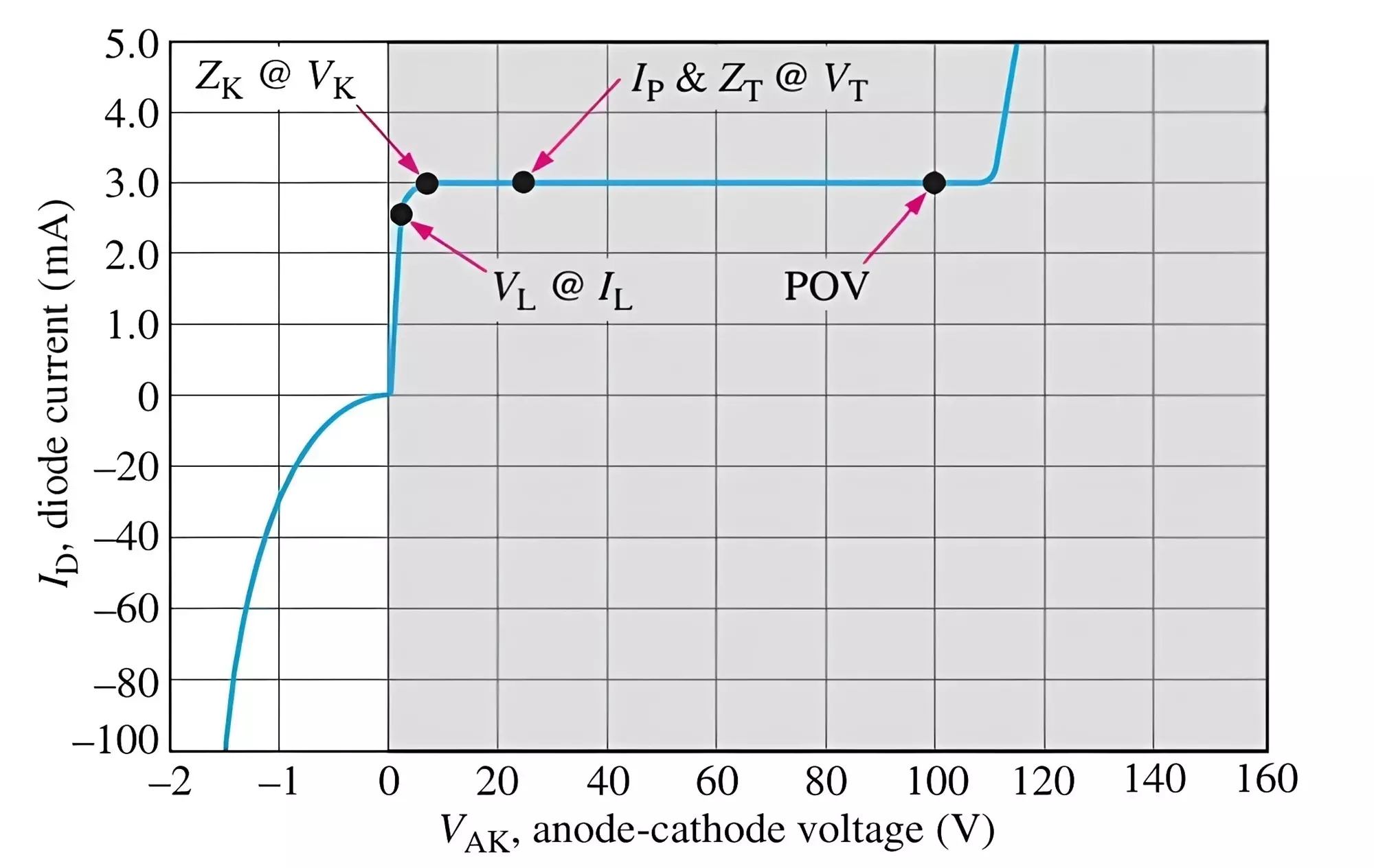
- The graph shows the characteristics of a Constant Current Diode (CCD), divided into three regions.
- Initially, current rises linearly (Ohmic).
- Then it flattens into a constant line (Current Regulation).
- Finally, it risks sudden rise (breakdown).
- In the shaded region, the diode operates under forward bias conditions.
- The forward current remains constant between 1.5V and 6V.
- This constant forward current is called the regulator current (Ip).
- The regulator current handled by the diode ranges from 220 µA to 4.7 mA.
- To obtain higher current levels, multiple diodes are connected in parallel.
- CCDs do not have a specified reverse breakdown voltage and are not intended for reverse-biased operation.
- Reverse current begins to increase when VAK drops below 0V.
- Under forward bias, regulation starts at the limiting voltage (VL) and continues up to the Peak Operating Voltage (POV).
- Between Vk and POV on the graph, the current remains constant.
- The test voltage (VT) is used to define the values of Ip and ZT as specified in the datasheet.
- For diode series 1N5283 to 1N5314, the dynamic impedance (ZT) ranges from 235 kΩ to 25 MΩ.
Important Parameters:
- Minimum Voltage (
Vk): Minimum voltage needed to achieve current regulation. - Maximum Voltage (
POV): Maximum safe operating voltage. - Regulated Current (
Ip): The constant current maintained.
Advantages of Constant Current Diode
- Simplicity: Easy to use; behaves like a two-terminal device without external biasing circuits.
- Stability: Provides highly stable current over a wide voltage range.
- Compact Size: Very small, allowing dense circuit designs.
- Low Cost: Economical for current regulation applications.
- Reliable: Long life when operated within specified limits.
- Temperature Compensation: Some CCDs are internally compensated for moderate temperature variations.
Disadvantages of Constant Current Diode
- Limited Current Range: Typically suited for small currents (few microamperes to tens of milliamperes).
- Voltage Limits: Sensitive to over-voltage, which can cause permanent damage.
- Temperature Sensitivity: Regulation may drift with high temperature changes (if not compensated).
- Unidirectional: Current regulation only in one direction (like a diode).
- Not Suitable for High-Power Applications: Mainly used for small-signal circuits.
Applications of Constant Current Diode
- ▶ LED Drivers: Provide constant current to LEDs ensuring consistent brightness and longer lifespan.
- ▶ Battery Charging: Used in trickle chargers to supply small, steady current without overcharging.
- ▶ Current Source Circuits: Acts as a simple current source for biasing transistors and op-amps.
- ▶ Analog Circuits: Used in analog meters, voltage references, and amplifier circuits requiring constant current bias.
- ▶ Test Equipment: Maintains a steady test current in measurement and calibration instruments.
- ▶ Photodiode Biasing: Provides a constant current bias for photodiodes in optical sensors.
- ▶ Precision Timers: In timing circuits where precise current charging / discharging is critical.
Conclusion
The Constant Current Diode is a simple, reliable, and efficient component that plays a critical role in electronic circuits where maintaining a steady current is essential. Its behavior is based on JFET properties, and it provides designers with an easy solution for current regulation without complex circuitry.
While they are limited to low-power applications, their advantages in terms of simplicity, size, and stability make CCDs an irreplaceable part of modern electronics.
Types of Diodes with Symbol, Definition, Working and Applications
Fast Recovery Diode Symbol, Construction, Working & Applications
VI Characteristics of Zener Diode, Working and its Applications
