This article describes a sensor-less BLDC motor driver circuit using 555 timer and DRV10866 motor driver IC, suitable for driving small 5V BLDC fans without position sensors.
The rise in the use of brushless DC motors (BLDCs) is driven by their efficiency, durability, and precision. However, controlling these motors typically requires rotor position information to select the appropriate commutation angle, usually obtained via Hall Effect sensors. In cost-sensitive applications, sensor-less commutation schemes are preferable.
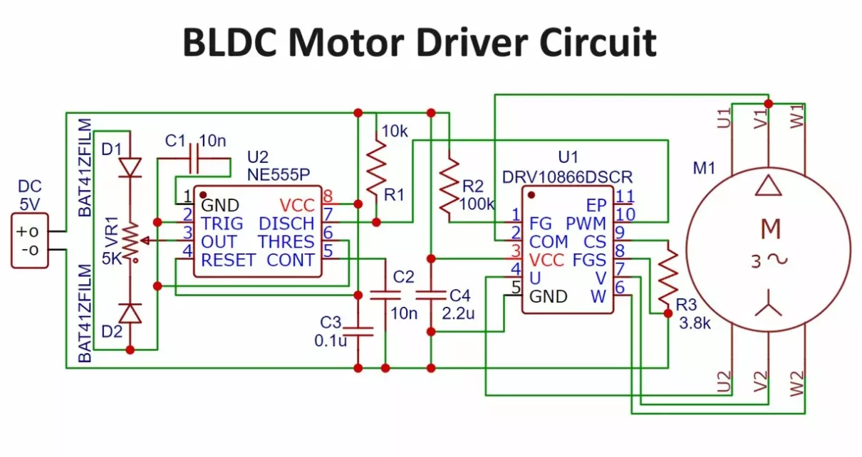
Brushless DC Motor Driver Circuit:

Components:
- NE555 Timer IC (IC1)
- DRV10866 Motor Driver IC (IC2)
- BLDC Motor (M1)
- Resistors, capacitors, potentiometer, and other passive components
Working Principle of BLDC Motor Driver Circuit:
The DRV10866 driver IC from Texas Instruments drives a three-phase BLDC motor. This IC features integrated power MOSFETs and supports up to 680mA peak current. It employs a 150° sensor-less back EMF scheme to control the motor.
Components List:
- Resistor 10 KΩ (R1) – 1 piece
- Resistor 100 KΩ (R2) – 1 piece
- Resistor 3.8 KΩ (R3) – 1 piece
- Variable Resistor 5 KΩ (VR1) – 1 piece
- Capacitor 10 nF (Ceramic Disc, C1 and C2) – 2 pieces
- Capacitor 0.1 µF (Ceramic Disc, C3) – 1 piece
- Capacitor 2.2 µF (Ceramic Disc, C4) – 1 piece
- NE555 Timer IC (IC1) – 1 piece
- BAT41 Schottky Diode (D1 and D2) – 2 pieces
- DRV10866 3-phase BLDC Motor Driver IC (IC2) – 1 piece
- 5V Power Supply (Battery/DC Adapter) – 1 piece
PCB Design:

NE555 Timer (IC1):
- Generates a pulse-width modulated (PWM) signal.
- Pin 7 (DIS) of IC1 outputs the PWM signal instead of the usual pin 3.
DRV10866 Motor Driver (IC2):
- Pin 1: Connected to a 100k pull-up resistor (R2).
- Pin 2, 4, 7, 6: Connected to common, phase A, phase B, and phase C of the BLDC motor, respectively.
- Pin 10: Receives the PWM signal from pin 7 of IC1.
PWM Control:
- The PWM signal’s frequency is approximately 25kHz.
- The duty cycle of the PWM signal can be adjusted from 5% to 95% using a potentiometer (VR1).
- Adjusting VR1 changes the motor speed:
- Turning VR1 counterclockwise decreases the duty cycle, lowering the motor speed.
- Turning VR1 clockwise increases the duty cycle, raising the motor speed.
Construction and Testing:
- You can see a double-sided PCB layout and component layout for accurate assembly.
- IC2 should be mounted on the top solder side of the PCB.

Testing Procedure:
- Connect a 5V DC Power supply to the connector.
- Adjust VR1 to vary the motor speed:
- Clockwise adjustment increases speed.
- Counter-clockwise adjustment decreases speed.
Conclusion on BLDC Motor Driver Circuit:
This brushless DC motor driver circuit efficiently controls a small BLDC fan using a sensor-less commutation scheme, making it suitable for cost-sensitive applications. The DRV10866 IC simplifies the design by integrating the necessary power MOSFETs and employing a 150° back EMF scheme, eliminating the need for rotor position sensors. The NE555 timer enables smooth PWM-based speed control, providing a reliable and adjustable solution for BLDC motor applications.
LED Chaser Circuit by 555 Timer

Hello,
I am looking for a small electronic board to control a small BLDC generator (MPPT) for a small wind generator.
Maybe someone can help me or support me in the development of this MPPT board.
with best regards
Sven
Come on WhatsApp to discuss further