A power diode is a semiconductor device specifically engineered to conduct large currents and withstand high reverse voltages in power electronic circuits. It is fundamentally a PN junction diode, but its internal structure, doping profile, and packaging are optimized for high-power operation rather than low-level signal processing.
In power electronic systems, power diodes play a critical role in electrical energy conversion by allowing current flow in one direction while blocking it in the opposite direction. They are classified as uncontrolled power devices because their conduction state depends entirely on the applied voltage polarity and magnitude, without any external control terminal.
Power diodes are widely used in rectifiers, DC power supplies, inverters, motor drives, battery chargers, UPS systems, welding equipment, and renewable energy conversion systems.
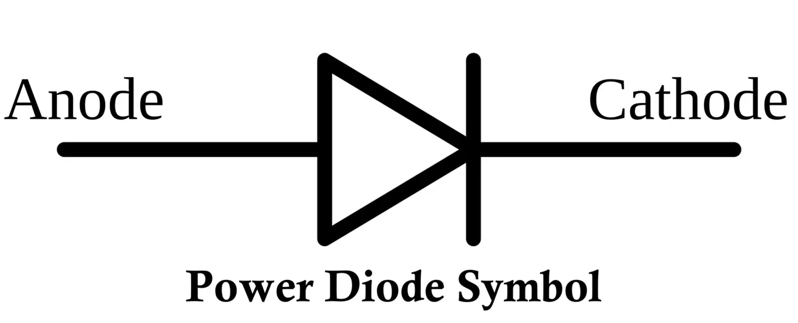
Symbol of Power Diode
The symbol of a power diode is identical to that of a conventional PN junction diode. It consists of two terminals known as the anode and the cathode.
Anode and Cathode Identification
The anode is connected to the P-type semiconductor region, while the cathode is connected to the N-type region. When the anode is positive with respect to the cathode, the diode conducts current.
Representation in Power Circuits
In power electronic circuit diagrams, the diode symbol is usually accompanied by electrical ratings such as current capacity, reverse voltage rating, and recovery characteristics rather than only a part number. This highlights its importance as a power-handling component rather than a simple signal device.
Related Articles:
- Difference Between Photodiode, Phototransistor and Photoresistor
- Constant Current Diode Symbol, Construction, Working & Applications
- Diode Clipper Circuit Diagram, Types, Working and Applications
- TVS Diode: Symbol, Construction, Working, Types and Applications
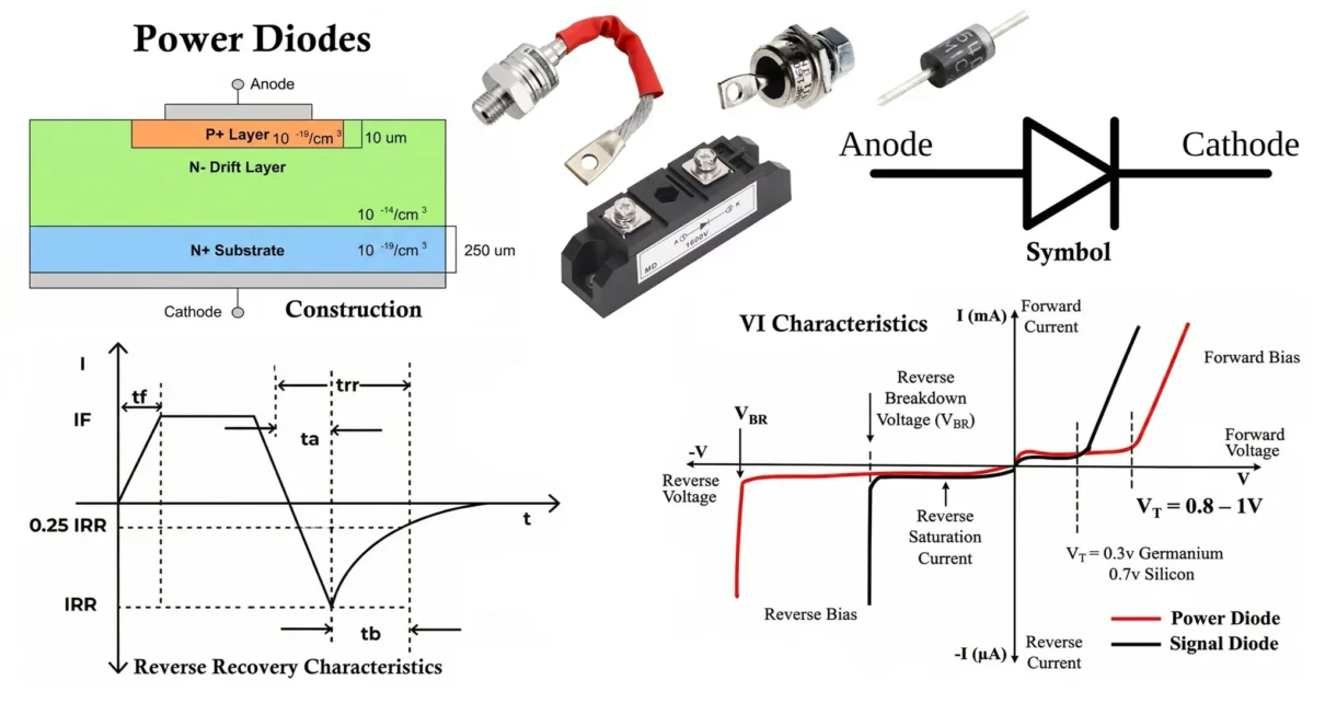
Construction of Power Diode
The construction of a power diode differs significantly from that of a small-signal diode due to the requirement for high voltage blocking and high current conduction.
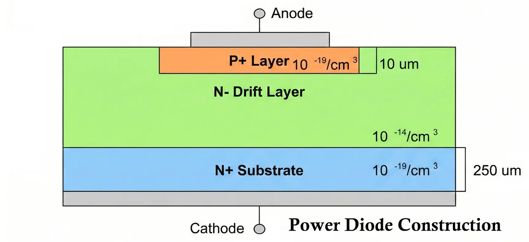
- Structural Arrangement: A typical power diode uses a P+N-N+ structure. This arrangement allows the diode to support high reverse voltages while maintaining acceptable forward conduction losses.
- P+ Region: The P+ region is heavily doped and forms the anode terminal of the diode. Heavy doping reduces contact resistance and ensures efficient current injection into the junction during forward bias operation.
- N- Drift Region: The N- region, also known as the drift region, is lightly doped and relatively thick. This region plays a crucial role in determining the reverse voltage capability of the diode. A thicker and lightly doped drift region allows the diode to withstand higher reverse voltages, but it also increases the forward voltage drop and conduction losses.
- N+ Region: The N+ region is heavily doped to provide a low-resistance cathode contact. This region improves current conduction and reduces power dissipation under forward bias conditions.
- Edge Termination and Field Control: To prevent premature breakdown at the edges of the junction, various edge termination techniques are employed, such as guard rings, field plates, and junction termination extensions. These structures help distribute the electric field uniformly across the junction when the diode is reverse biased.
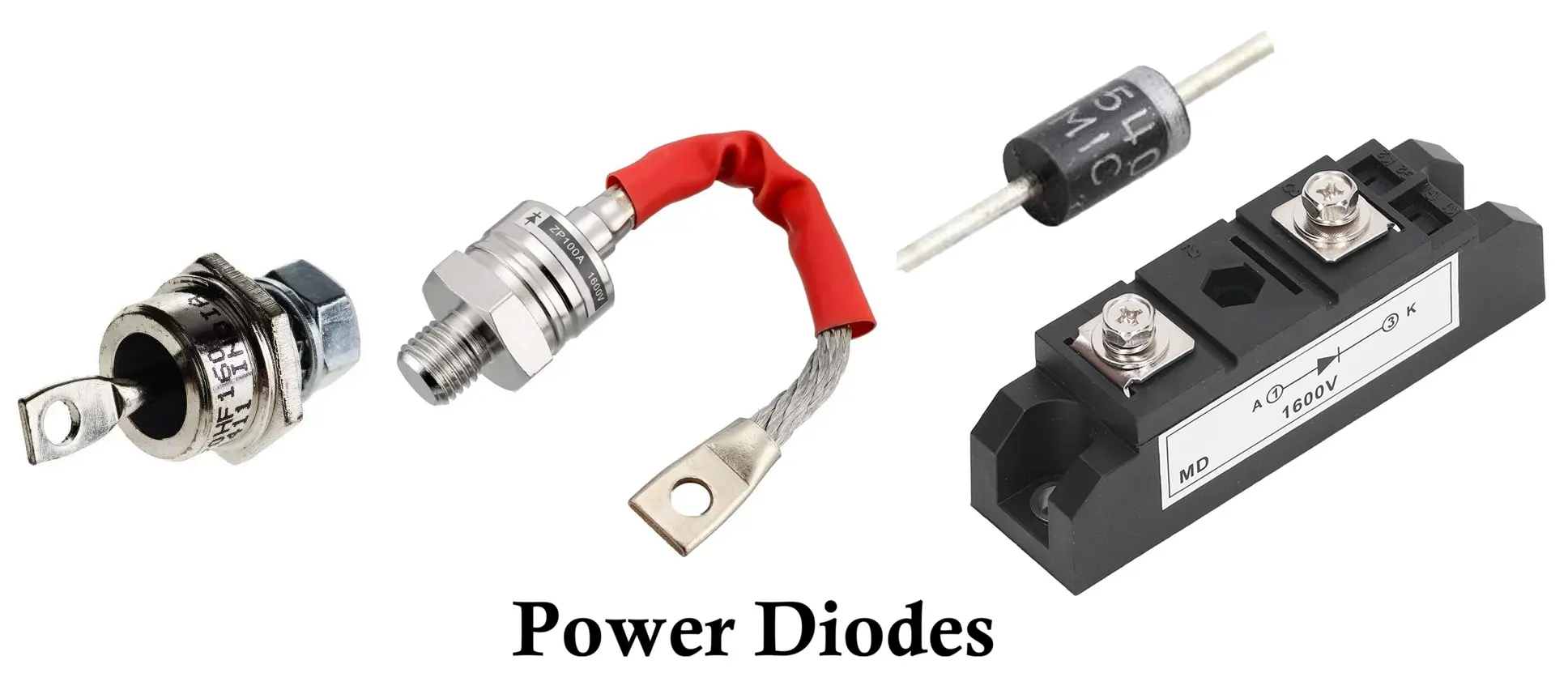
- Packaging and Thermal Design: Power diodes are packaged in mechanically robust enclosures such as stud-mounted, press-pack, disc-type, and module packages. These packages are designed to provide low thermal resistance and enable efficient heat transfer to external heat sinks.
Working of Power Diode
The operation of a power diode can be understood by analyzing its behavior under forward bias and reverse bias conditions.
Forward Bias Operation
When the anode is made positive with respect to the cathode, the PN junction becomes forward biased. The depletion region narrows, allowing majority charge carriers to cross the junction. As a result, the diode conducts current.
The forward voltage drop of a power diode is higher than that of a small-signal diode due to the presence of the thick drift region. Typical forward voltage values range from approximately 0.8 V to 1.2 V for silicon power diodes. This voltage drop increases with current and temperature, resulting in conduction losses that must be managed using proper cooling techniques.
Reverse Bias Operation
When the cathode is positive with respect to the anode, the PN junction becomes reverse biased. The depletion region widens and the diode blocks current flow. Only a small reverse leakage current flows due to minority charge carriers.
The diode can safely block voltage up to its maximum rated reverse voltage. If this voltage is exceeded, avalanche breakdown occurs. Power diodes are generally designed to tolerate limited avalanche conditions, provided the resulting current and energy dissipation remain within specified limits.
VI Characteristics of Power Diode
The VI (voltage – current) characteristics of a power diode explain how the diode behaves under different operating conditions by showing the relationship between the applied voltage and the resulting current.
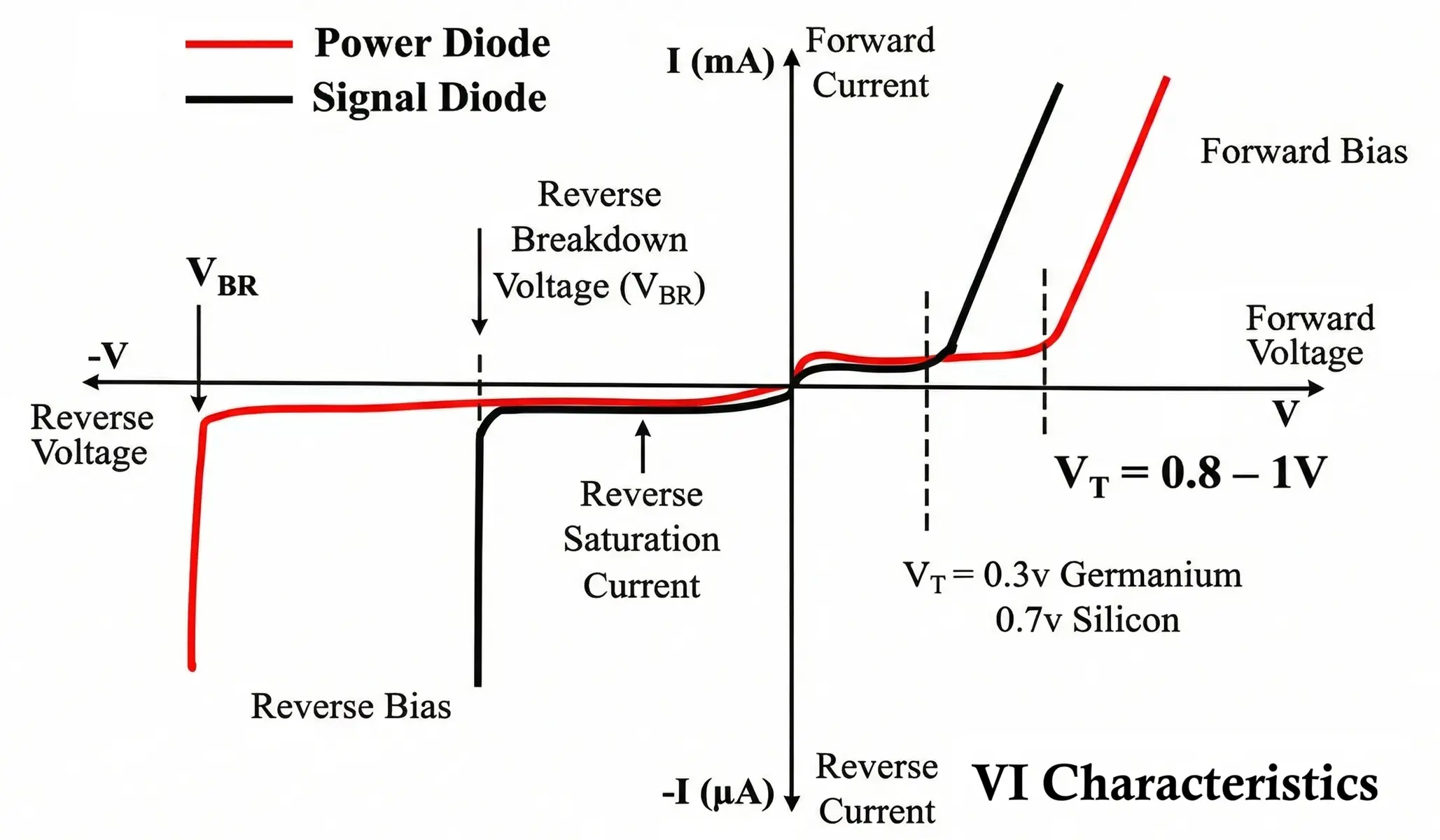
Forward Characteristics
- In the forward region, the current increases exponentially once the threshold voltage is exceeded. However, the slope of the forward characteristic is lower than that of signal diodes due to higher series resistance introduced by the drift region.
- When the source voltage (Vs) increases from zero up to the cut-in voltage, the forward current through the diode remains extremely small. The cut-in voltage, also referred to as the threshold voltage or turn-on voltage is the minimum forward voltage required for the diode to begin conducting.
- Once the applied voltage exceeds the cut-in value, the diode current rises rapidly and conduction begins. For a silicon diode, the cut-in voltage is typically around 0.7 V. During conduction, the diode exhibits a forward voltage drop in the range of approximately 0.8 V to 1 V.
- In high-power diodes, the forward current increases almost linearly with an increase in forward voltage. In contrast, low-power diodes show an initial exponential rise in current with voltage, which later becomes nearly linear as the voltage continues to increase.
Reverse Characteristics
- In the reverse region, the current remains very small until the breakdown voltage is reached. At breakdown, a sharp increase in current occurs. Properly designed power diodes can survive repetitive avalanche breakdown if the associated energy dissipation is controlled.
- Under reverse-biased conditions, a very small current known as leakage current flows through the diode. This leakage current remains nearly constant and is largely independent of the applied reverse voltage until the breakdown voltage is reached.
- At breakdown, the reverse voltage stays almost constant while the reverse current increases sharply, limited only by the external circuit resistance.
- To ensure safe operation, the diode must be operated below its peak reverse repetitive voltage (VRRM). The peak inverse voltage (PIV) represents the maximum reverse voltage a diode can withstand during normal operation and is equivalent to VRRM.
Reverse Recovery Phenomenon
When a power diode conducting in forward bias is suddenly reverse biased, it does not immediately stop conducting. Stored charge carriers within the junction must first be removed. During this interval, a reverse current flows for a short duration known as the reverse recovery time.
Reverse recovery causes additional power losses, voltage overshoot, electromagnetic interference, and stress on associated switching devices. This phenomenon limits the suitability of conventional silicon power diodes for high-frequency switching applications.
Reverse Recovery Characteristics of Power Diode
Reverse recovery characteristics describe the behavior of a power diode when it transitions from the conducting (forward-biased) state to the non-conducting (reverse-biased) state.
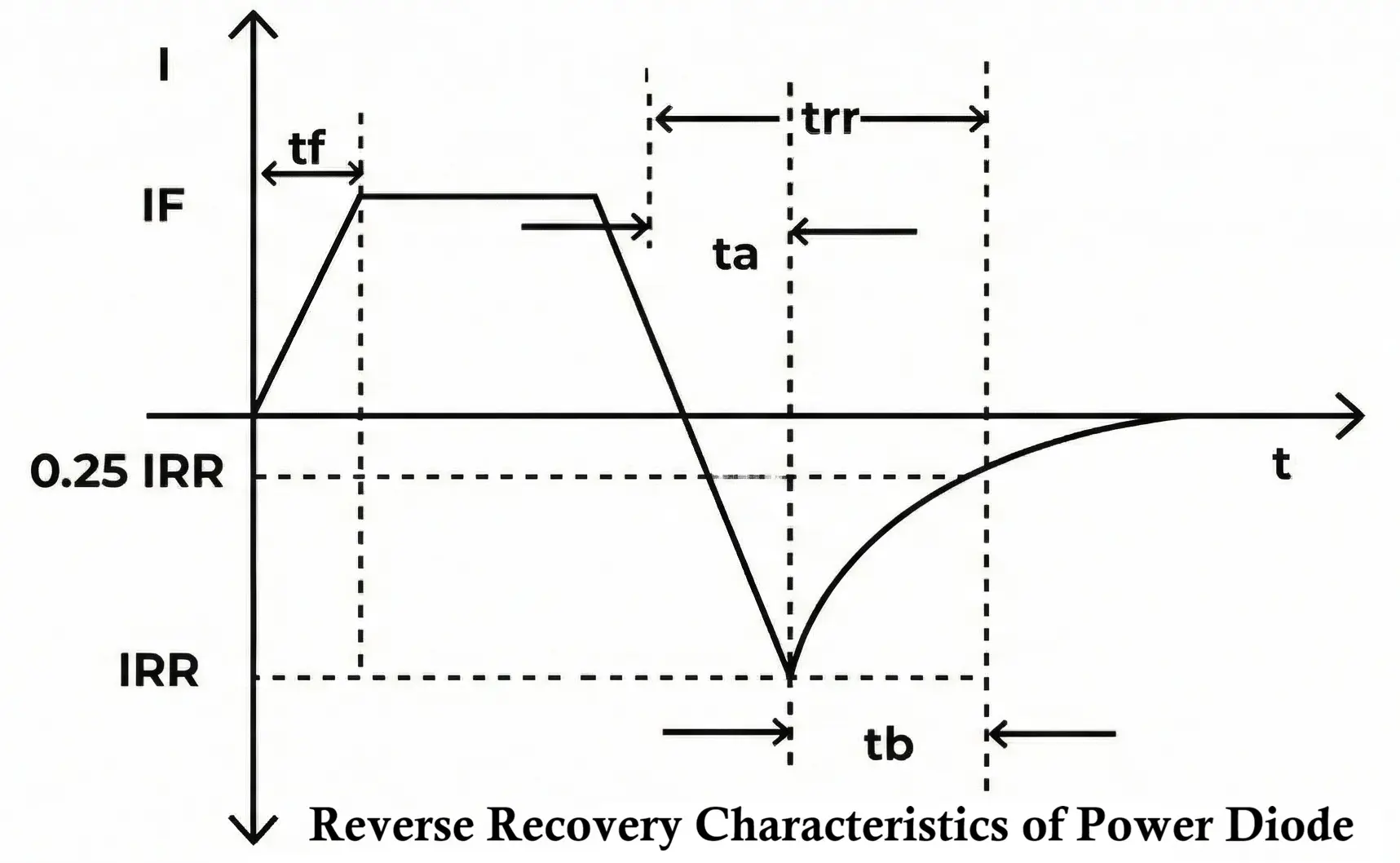
- When a diode is forward-biased, it allows current to flow easily. However, when the polarity is reversed, the diode does not stop conducting instantaneously. Instead, there is a short interval during which it continues to conduct in the reverse direction.
- This interval is known as the reverse recovery time (trr) and occurs because charge carriers (electrons and holes) stored in the diode take time to be removed.
- The reverse recovery time is an important parameter, especially in high-frequency and power-electronic applications, because the diode continues to conduct during this period, potentially causing switching losses and unwanted power dissipation.
- Reverse recovery behavior is represented by graph showing reverse recovery current (IRR) and reverse recovery time. The reverse recovery current is the transient current that flows briefly after the diode is reverse-biased.
- To reduce the effects of reverse recovery, use fast-recovery or ultra-fast-recovery diodes, particularly in applications that require rapid switching or low power losses.
- Even after the forward current (IF) falls to zero, the diode continues to conduct briefly in the reverse direction due to stored charge in the depletion region and semiconductor layers.
- The diode fully regains its blocking ability only when the reverse recovery current decays to zero.
- The reverse recovery time (trr) is defined as the time interval from when the forward current becomes zero to the point where the reverse recovery current falls to 25% of its peak value.
- During the time interval ta, the charge stored in the depletion region is removed. During tb, the charge stored in the semiconductor layers is eliminated.
Types of Power Diodes
Power diodes are semiconductor devices specifically designed to handle high current and high voltage in power electronic circuits. Based on their internal construction, switching behavior, and recovery characteristics, power diodes are classified into several types. Each type is suitable for particular applications such as rectification, switching, protection, and voltage regulation.
1. General Purpose Power Diodes
General purpose power diodes are the most commonly used type of power diodes. They are designed to withstand high forward current and high reverse voltage, but they exhibit relatively slow switching characteristics.
These diodes have a large junction area, which allows them to handle substantial power levels. However, due to the large amount of stored charge in the junction, they have a long reverse recovery time, making them unsuitable for high-frequency applications.
- High forward current and reverse voltage ratings
- Long reverse recovery time (slow switching)
- Robust and reliable for continuous operation
- Mainly used in low-frequency circuits
Applications: Line-frequency rectifiers, power supplies, battery chargers, and uncontrolled rectifier circuits operating at 50 Hz or 60 Hz.
2. Fast Recovery Power Diodes
Fast recovery power diodes are an improved version of general-purpose diodes, specifically designed to reduce reverse recovery time. This is achieved by modifying the internal structure of the diode to minimize charge storage.
Because of their shorter reverse recovery time, fast recovery diodes significantly reduce switching losses and electromagnetic interference (EMI) in power electronic circuits.
- Short reverse recovery time compared to general purpose diodes
- Lower switching losses
- Better performance at medium to high switching frequencies
Applications: Inverters, choppers, DC–DC converters, SMPS (Switched Mode Power Supplies), and freewheeling diodes in power circuits.
3. Schottky Power Diodes
Schottky power diodes differ from conventional PN-junction diodes in that they use a metal–semiconductor junction instead of a PN junction. Due to this structure, Schottky diodes do not store charge in the junction.
As a result, Schottky diodes exhibit virtually zero reverse recovery time and have a very low forward voltage drop, which leads to higher efficiency and reduced power losses.
- Negligible reverse recovery time
- Low forward voltage drop (typically 0.2 V to 0.4 V)
- High switching speed
- Higher leakage current compared to PN diodes
- Lower reverse voltage ratings
Applications: Low-voltage, high-current power supplies, DC–DC converters, rectifiers in SMPS, and high-efficiency power circuits.
4. Avalanche Power Diodes
Avalanche power diodes are designed to operate safely in the avalanche breakdown region. Unlike ordinary diodes, which may get damaged during breakdown, avalanche diodes can withstand sudden voltage spikes without failure.
These diodes are manufactured with controlled doping profiles that allow uniform breakdown across the junction, preventing localized overheating and damage.
- High surge current handling capability
- Can safely operate in avalanche breakdown
- High reliability and rugged construction
Applications: Voltage clamping circuits, surge protection, snubber circuits, and protection of power electronic devices from transient overvoltage.
5. Silicon Carbide (SiC) Power Diodes
Silicon Carbide (SiC) power diodes are advanced semiconductor devices manufactured using wide bandgap Silicon Carbide material instead of conventional silicon. Due to their superior material properties, SiC power diodes offer significantly improved performance in high-voltage, high-frequency, and high-temperature applications.
Most SiC power diodes are Schottky-type devices, which means they employ a metal-semiconductor junction rather than a traditional PN junction. As a result, SiC power diodes exhibit negligible reverse recovery current and extremely fast switching behavior, leading to reduced switching losses and improved overall system efficiency.
Unlike silicon diodes, SiC power diodes can operate at much higher junction temperatures and withstand higher electric fields. This allows them to be used in compact, high-power-density systems with reduced cooling requirements.
- Wide bandgap semiconductor material
- Nearly zero reverse recovery time
- High breakdown voltage capability
- High switching speed and low switching losses
- High operating temperature (typically above 200°C)
- Excellent thermal conductivity
Applications: Electric vehicle (EV) powertrains, high-frequency DC-DC converters, solar inverters, wind energy systems, industrial motor drives, and aerospace power electronics.
Advantages of Power Diodes
Power diodes offer robust construction and ability to handle high electrical stress allow reliable operation in demanding environments.
- Capable of handling high forward current and high reverse voltage
- Simple structure and easy to use in circuits
- High reliability and long operational life
- Low cost compared to other power semiconductor devices
- Efficient rectification of AC to DC
- Available in a wide range of voltage and current ratings
Disadvantages of Power Diodes
Power diodes have certain limitations that must be considered during circuit design and component selection.
- Unidirectional current conduction only
- Forward voltage drop leads to power loss and heat generation
- Reverse recovery time causes switching losses in high-frequency applications
- Requires heat sinks for high-power operation
- Limited control compared to controllable devices like thyristors and transistors
Applications of Power Diodes
Power diodes are widely used in various power electronic and industrial applications due to their ability to efficiently control and convert electrical power.
- AC to DC rectifiers in power supplies
- Freewheeling diodes in inductive load circuits
- Battery charging circuits
- Snubber and clamping circuits for voltage protection
- DC–DC converters and inverters
- Motor drives and industrial control systems
- Renewable energy systems such as solar and wind power
- Electric vehicle power electronics
Selection Criteria for Power Diodes
- Voltage Rating: The diode’s maximum repetitive reverse voltage (VRRM) should be higher than the maximum reverse voltage in the circuit.
- Current Rating: The average forward current rating must exceed the maximum load current to ensure safe operation.
- Surge Current Capability: The diode should withstand high inrush or fault currents without damage.
- Forward Voltage Drop: Lower forward voltage drop reduces conduction losses and improves efficiency.
- Reverse Recovery Time: Fast recovery time is essential for high-frequency switching applications.
- Power Dissipation: The diode must be capable of dissipating the heat generated during operation.
- Thermal Characteristics: Adequate thermal resistance and heat-sinking capability are necessary to keep junction temperature within safe limits.
- Operating Frequency: General purpose diodes are suitable for low frequencies, while fast recovery or SiC diodes are preferred for high-frequency applications.
- Operating Temperature: The diode should operate reliably within the expected ambient and junction temperature range.
- Application Requirement: The diode type should be selected based on specific application needs such as rectification, freewheeling, protection, or high-efficiency switching.
Conclusion
The power diode is one of the most fundamental and indispensable components in power electronics. Its ability to handle high current and high voltage, combined with simple operation and robust construction, ensures its continued relevance in modern electrical and electronic systems. A thorough understanding of its construction, working principles, characteristics, parameters, and limitations is essential for designing efficient, reliable, and safe power electronic circuits.
1N5400, 1n5820, STTH2002, MBR20100CT, BYW29 are some of the popular power diode types.
Types of Diodes with Symbol, Definition, Working and Applications
Photodiode – Symbol, Construction, Working, Types and Applications
Step Recovery Diode Symbol, Construction, Working & Applications
Laser Diode – Symbol, Construction, Working, Types and Applications
