RC filters are the most fundamental signal-processing circuits in electronics. It uses a combination of a resistor (R) and a capacitor (C) to selectively allow or suppress signals based on their frequency. Despite its simplicity, the RC filter plays a crucial role in almost every electronic system, from basic audio amplifiers to complex communication and measurement equipment.
Filtering is required in electronic systems to remove unwanted frequency components, suppress noise, smooth pulsating voltages, and isolate useful signals from interference. Without filtering, electronic circuits would be vulnerable to distortion, instability, and noise contamination.
Historically, RC filters emerged alongside early radio and telecommunication systems, where frequency selection and noise suppression became essential. Even with the availability of sophisticated digital filters and active filter circuits today, RC filters remain relevant due to their simplicity, low cost, reliability, and ease of implementation.
Passive Components of RC Circuit
Resistor (R)
A resistor opposes the flow of electric current and produces a voltage drop proportional to current according to Ohm’s law:
V = IR
Resistors dissipate energy in the form of heat, and their behavior is independent of frequency (ideal case).
Capacitor (C)
A capacitor stores electrical energy in the form of an electric field between two plates. Its ability to store charge is defined by capacitance:
Q = CV
Capacitors oppose changes in voltage and exhibit frequency-dependent behavior.
Capacitive Reactance
The opposition offered by a capacitor to alternating current is called capacitive reactance, given by:
XC = 1/2πfC
Where:
- f = frequency Hz
- c = capacitance F
As frequency increases, capacitive reactance decreases, allowing higher-frequency signals to pass more easily.
Frequency Domain Concept
RC filters operate on the principle that resistors respond equally to all frequencies, while capacitors respond differently at different frequencies. This frequency-dependent impedance forms the basis of filtering and is best analyzed using frequency-domain techniques.
What Is an RC Filter?
An RC filter is a first-order passive filter composed of one resistor and one capacitor arranged to control the frequency response of a signal.
Passive vs Active Filters:
- Passive filters use only R, L, and C components and do not require an external power supply.
- Active filters use active devices such as operational amplifiers along with passive components.
RC filters are called first-order filters because they contain only one energy storage element (capacitor), resulting in a roll-off rate of 20 dB per decade.
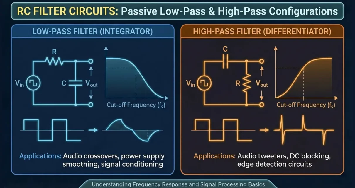
Types of RC Filters
Low-Pass RC Filter
Circuit Diagram
A low-pass RC filter consists of a resistor in series with the input and a capacitor connected to ground, with output taken across the capacitor.
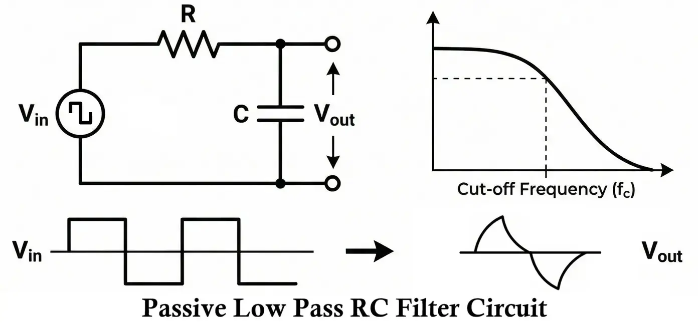
Principle of Operation
- At low frequencies, the capacitor offers high reactance, allowing the signal to appear at the output.
- At high frequencies, the capacitor offers low reactance and shunts the signal to ground.
Transfer Function
H(s) = 1/1 + sRC
Cutoff Frequency
fc = 1/2πRC
Magnitude and Phase Response
- Gain decreases beyond cutoff frequency
- Phase shifts from 0° to −90°
High-Pass RC Filter
Circuit Diagram
A high-pass RC filter has a capacitor in series with the input and a resistor connected to ground, with output taken across the resistor.
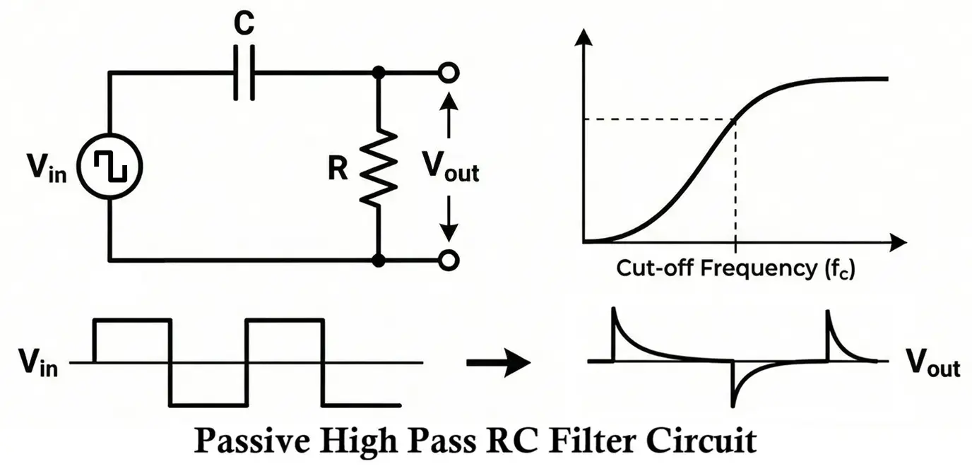
Principle of Operation
- At low frequencies, capacitive reactance is high, blocking the signal.
- At high frequencies, capacitive reactance is low, allowing signal passage.
Transfer Function
H(s) = sRC/1 + sRC
Magnitude and Phase Response
- Gain increases with frequency
- Phase shifts from +90° to 0°
Band-Pass and Band-Stop RC Filters
By cascading high-pass and low-pass RC sections, band-pass or band-stop responses can be approximated. However, passive RC band-pass filters suffer from Low gain, Wide bandwidth and Poor selectivity.
Mathematical Analysis
Using the voltage divider rule, the output voltage of an RC filter can be derived by treating the capacitor as an impedance.
H(jω) = ZC / (R + ZC)
Since:
ZC = 1 / (jωC)
H(jω) = 1 / (1 + jωRC)
Magnitude:
|H(jω)| = 1 / √(1 + (ωRC)2)
Phase:
φ = −tan−1(ωRC)
Cutoff Frequency
The cutoff frequency is defined as the frequency at which the output power drops to half of its maximum value,
or equivalently, the output voltage drops to 1/√2 of the input (−3 dB point).
fc = 1 / (2πRC)
Increasing R or C decreases the cutoff frequency fc, while decreasing them increases fc.
Design Procedure for RC Filter
- Specify the required cutoff frequency fc.
- Choose a convenient capacitor value C.
- Calculate the resistor value: R = 1 / (2πfcC)
- Select the nearest standard resistor value.
- Verify frequency response.
Example Design
Given: fc = 1 kHz, C = 0.01 µF (Chosen)
Calculate:
R = 1 / (2π(1000)(0.01 × 10⁻⁶))
≈ 15.9 kΩ
Select the nearest standard value:
R = 16 kΩ
Frequency Response of RC Filters
RC Low-Pass Filter (LPF)
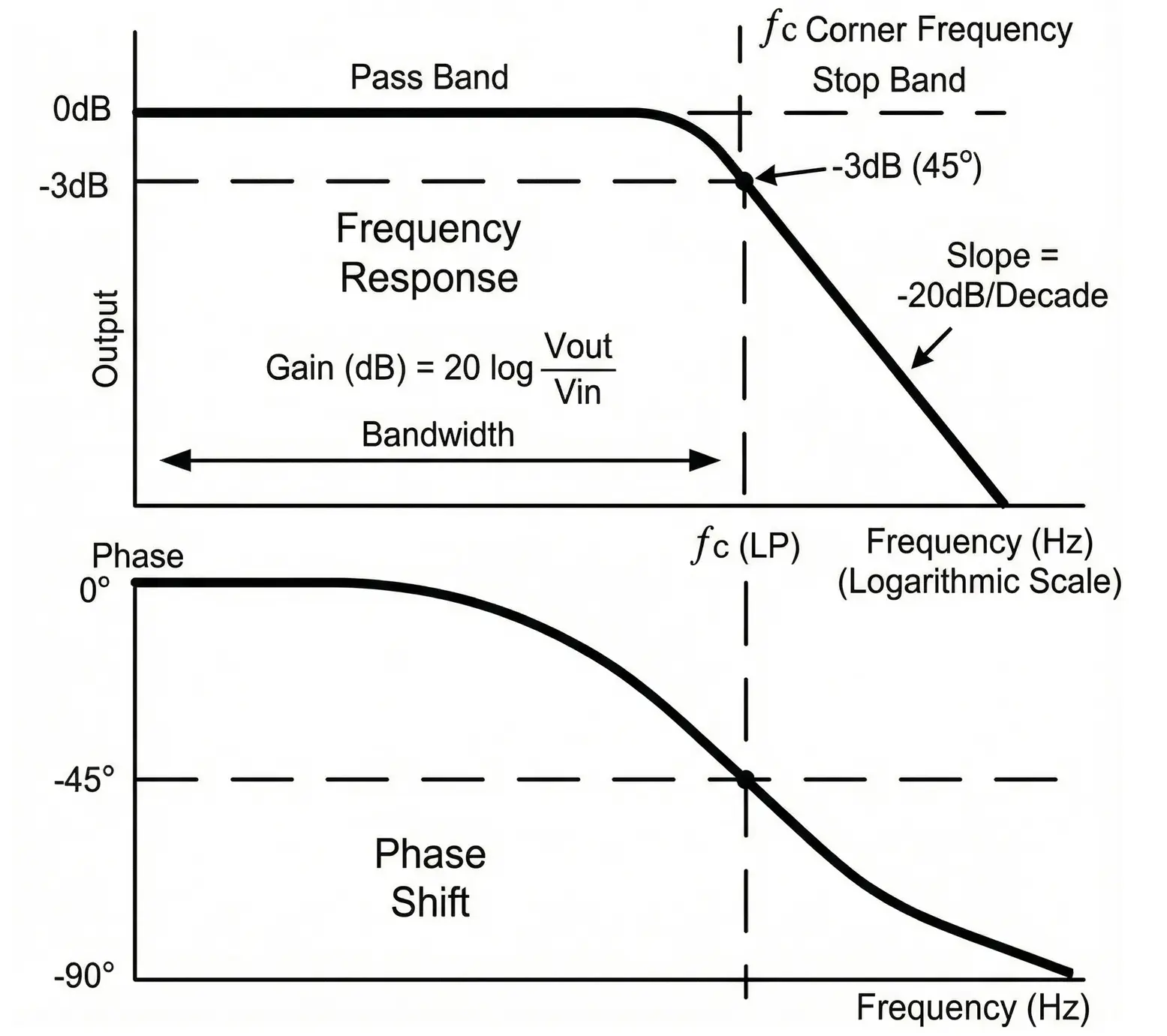
Magnitude Response
- Low frequencies (ω ≪ 1/RC): Output ≈ input (|H(jω)| ≈ 1).
- Cutoff frequency (ω = 1/RC): Output drops to 1/√2 of input (−3 dB point).
- High frequencies (ω ≫ 1/RC): Output decreases at −20 dB/decade.
Phase Response
- Starts at 0° (low frequency).
- Equals −45° at cutoff.
- Approaches −90° at high frequency.
RC High-Pass Filter (HPF)
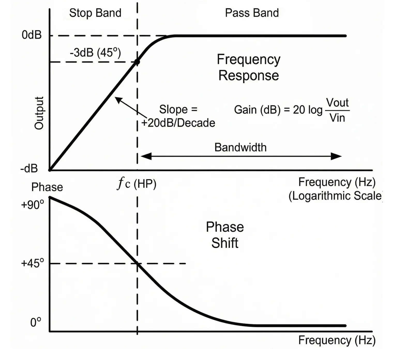
Magnitude Response
- Low frequencies: Output ≈ 0 (signal attenuated).
- Cutoff frequency: Output is 1/√2 of input (−3 dB).
- High frequencies: Output ≈ input (|H(jω)| ≈ 1).
Phase Response
- Starts at +90° (very low frequency).
- Equals +45° at cutoff.
- Approaches 0° at high frequency.
Cutoff Frequency
- For both LPF and HPF fc = 1/2πRC
- Increasing R or C → lowers (fc)
- Decreasing R or C → raises (fc)
Practical Considerations
- Component tolerances affect cutoff accuracy
- Temperature affects capacitance
- Parasitic elements limit high-frequency performance
- Source and load impedance cause loading effects
- Noise considerations in low-level signals
Advantages of RC Filters
- Simple circuit design using only resistors and capacitors
- Low cost and easy availability of components
- Compact size, suitable for small electronic devices
- No inductors required, avoiding magnetic interference
- Easy to design and analyze
- Suitable for low-frequency applications
Disadvantages of RC Filters
- Limited to low-frequency operation (ineffective at high power or high frequency)
- Signal attenuation occurs even in the passband
- Poor selectivity compared to LC or active filters
- Cannot provide gain (passive circuit)
- Load dependency affects cutoff frequency and response
- Power loss due to resistive elements
Applications of RC Filters
- Audio frequency filtering (tone control circuits)
- Noise reduction and signal smoothing
- Coupling and decoupling circuits
- Power supply ripple filtering
- Signal conditioning in analog circuits
- Timing and waveform shaping circuits
- Communication circuits for low-frequency signal filtering
Conclusion
RC filters are simple and economical circuits that use resistors and capacitors to control the frequency content of electrical signals. Their ease of design, compact size, and stable performance make them well suited for low-frequency applications such as audio processing, noise reduction, signal smoothing, and basic signal conditioning in analog systems.
However, RC filters have inherent limitations, including passband attenuation, limited selectivity, and the inability to provide signal gain since they are passive circuits. Despite these drawbacks, RC filters continue to be widely used where simplicity, reliability, and low cost are more important than sharp frequency response or high-power handling.
Types of Filter Circuits: Working Principles, Formula & Applications
Types of Capacitors with Symbol, Classification and Applications
Difference Between Coupling, Decoupling, and Bypass Capacitors
Types of Resistors with Symbol, Classification and Applications
