
Voltage multiplier circuit forms a fundamental building block in high-voltage power supplies where the output voltage must be several times greater than the peak input voltage, yet the load current required is relatively small. Instead of using high-turn-ratio transformers which are large, expensive, and limited by insulation and core saturation constraints engineers often implement multipliers using cascaded diode-capacitor networks.
These circuits originated from classical electrostatic research, most notably the Cockcroft–Walton generator, introduced in the 1930s. They remain in extensive use today in oscilloscopes, ionizers, X-ray equipment, laser power supplies, microwave ovens, photomultiplier tubes, electrostatic precipitators, and other systems requiring stable, kilovolt-range DC voltages.
This article explores the topology, construction practices, operational theory, engineering challenges, analytical equations, and application insights relevant to voltage multipliers.
Introduction to Voltage Multipliers
A voltage multiplier is a rectifying circuit composed of diodes and capacitors. It converts an AC input into a DC output that may be two, three, or many times higher than the peak AC voltage. The output voltage in an ideal scenario is:
Vout(ideal) ≈ n × Vpeak
where n is the number of multiplier stages.
Voltage multipliers generally operate at very low load currents and exhibit significant voltage drop under load. As such, they are not replacements for regulated DC-DC converters in medium- or high-current applications.
Types of Voltage Multipliers
There are several common multiplier architectures:
- Half-wave voltage doubler
- Full-wave voltage doubler
- Tripler and quadrupler topologies
- Cascade or Cockcroft–Walton ladder multiplier
- Delon circuit
- Villard cascade
- Greinacher doubler
All are based on Villard and Greinacher rectifier principles, differing primarily in capacitor placement, conduction phases, and ripple behavior.
1. Half Wave Voltage Multiplier Circuit
Here we are taking an example of half wave voltage doubler
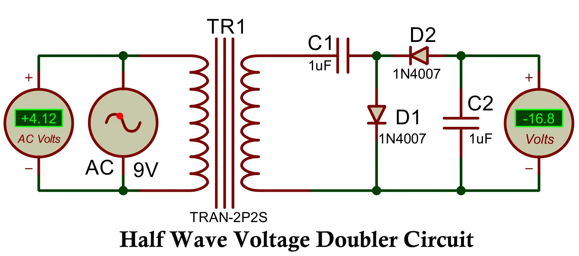
Components: Two diodes (D1, D2) and two capacitors (C1, C2).
Operation:
- Positive Half-Cycle
- D1 conducts.
- C1 charges to the peak input voltage (Vp).
- Negative Half-Cycle
- D1 is reverse-biased.
- D2 conducts.
- The input voltage and the stored voltage on C1 add, charging C2 to approximately 2Vp (minus diode drops).
Output Voltage:
Vout ≈ 2Vp
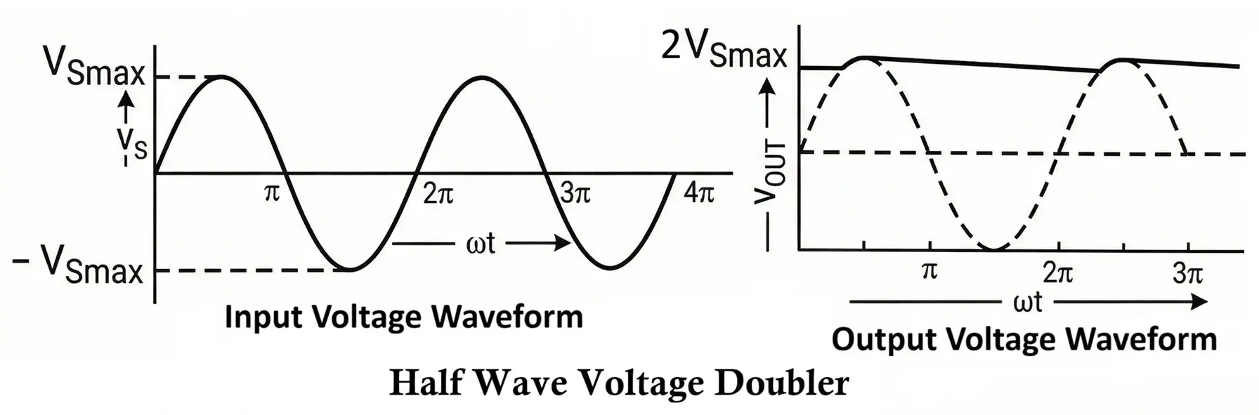
Waveform Summary:
- Input: sinusoidal AC.
- C1: charges to (Vp) during positive half-cycles.
- Output: a DC level near (2Vp) with noticeable ripple because only half of the AC cycle contributes to charging.
2. Full Wave Voltage Multiplier Circuit
Here we are taking an example of full wave voltage doubler
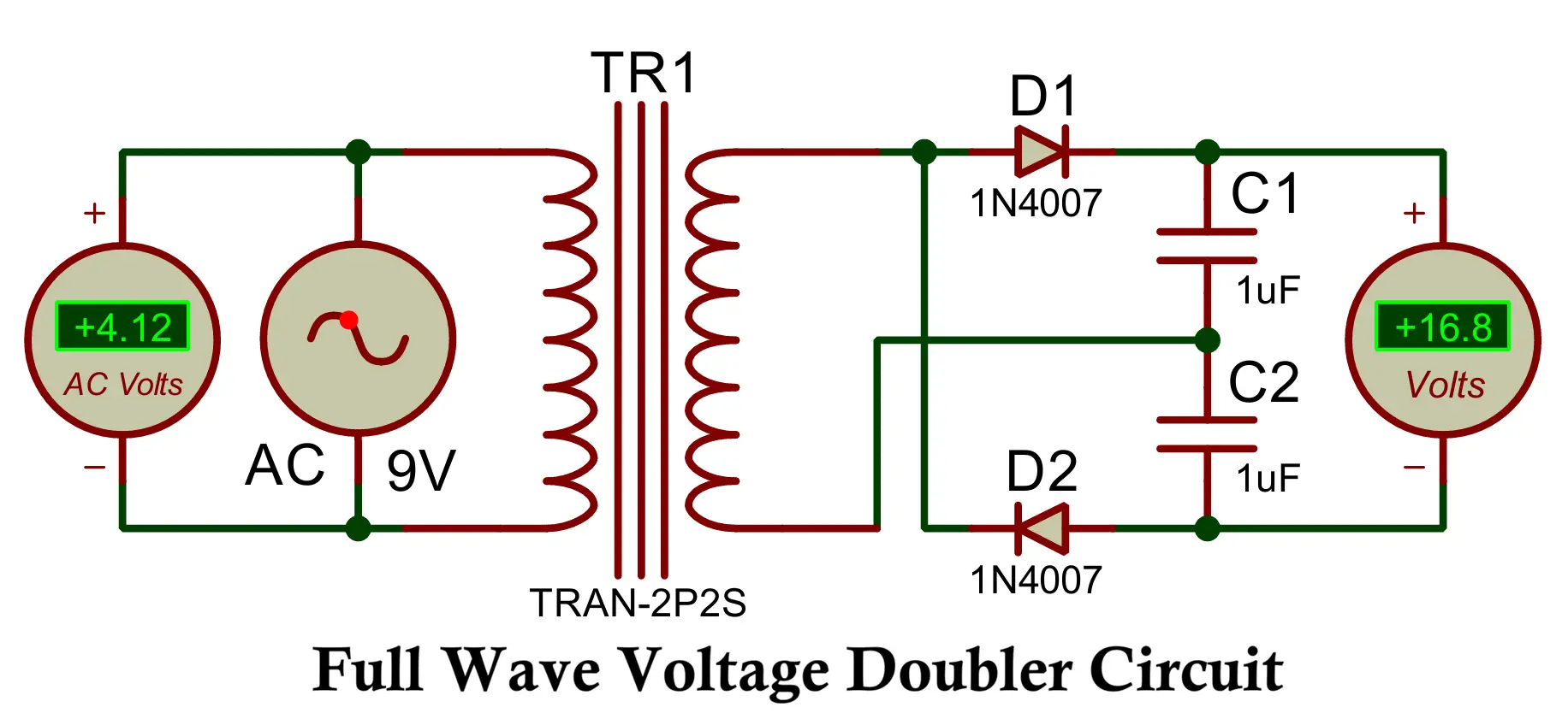
Components: Two diodes (D1, D2) and two capacitors (C1, C2).
Operation:
- Positive Half-Cycle
- D1 conducts.
- C1 charges to (V_p).
- Negative Half-Cycle
- D2 conducts.
- C2 charges to (Vp).
The output is taken across the series combination of C1 and C2, resulting in approximately (2Vp).
Output Voltage:
Vout ≈ 2Vp
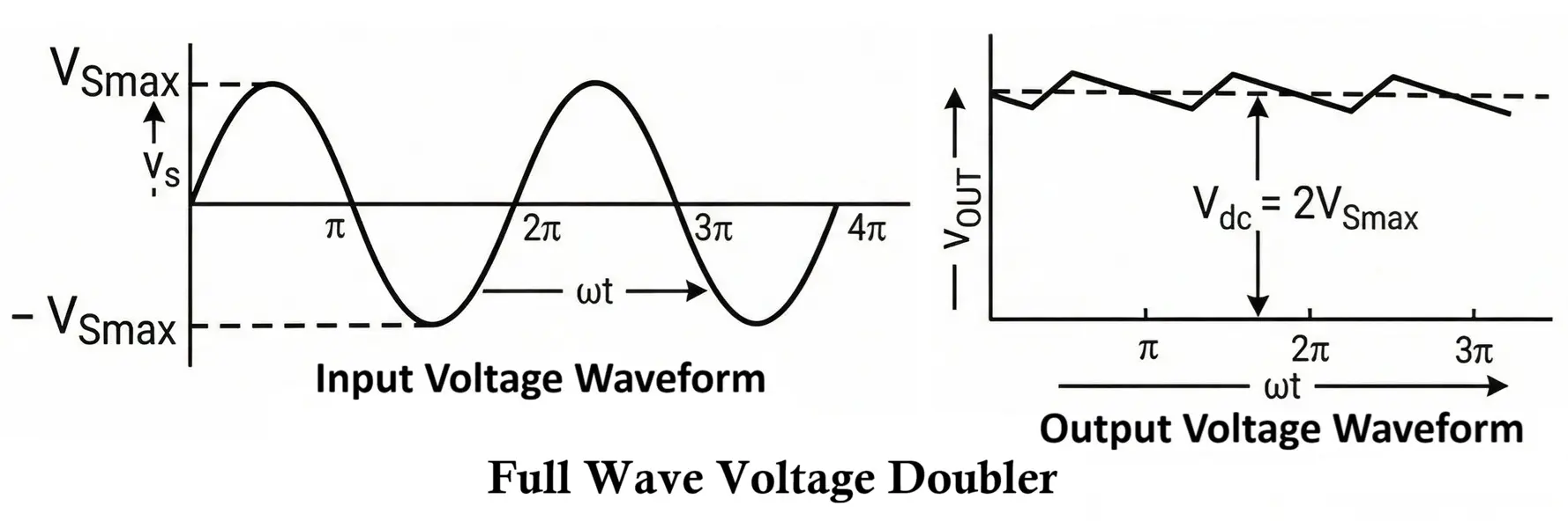
Waveform Summary:
- Both half-cycles charge capacitors.
- Ripple is lower compared to the half-wave doubler due to continuous charging.
Key Differences
| Parameter | Half-Wave Multiplier | Full-Wave Multiplier |
|---|---|---|
| Charging | Uses one half-cycle | Uses both half-cycles |
| Ripple | Higher | Lower |
| Efficiency | Lower | Higher |
| Output Smoothing | Poorer | Better |
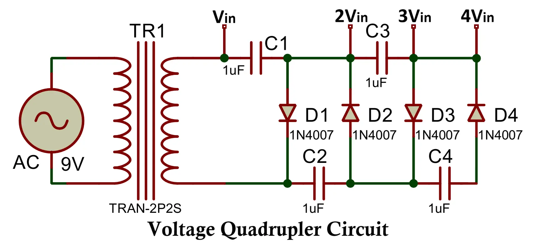
3. Tripler and Quadrupler Circuits
Higher-order multipliers (tripler, quadrupler, etc.) can be formed by cascading stages, commonly used where high DC voltages are required without a high-voltage transformer.
Typical application:
- CRT anode supplies (10–25 kV)
- High-voltage biasing systems
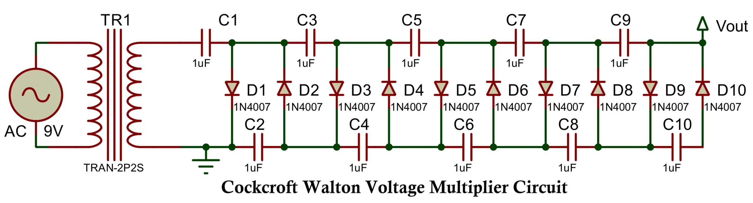
4. Cockcroft–Walton Cascade Multiplier
The most widely used high-voltage generator.
Advantages:
- Scalable to very high voltages
- No transformer needed
Disadvantages:
- Significant output sag at even small load currents
- Internal impedance increases rapidly with number of stages
Construction of Voltage Multiplier Circuit
Voltage multipliers must be engineered with attention:
1. Diode Selection
Key diode parameters:
- Peak Inverse Voltage (PIV)
For an n-stage CW multiplier, the maximum reverse voltage across the first diode can be approximated by: PIVmax ≈ 2 × n × Vpeak - Forward recovery and reverse recovery time
High-frequency multipliers require fast diodes (UF4007, HER series, or dedicated HV rectifiers). - Junction temperature rating
Heat dissipation is crucial in multi-kilovolt systems due to conduction losses and leakage. - Leakage current
Leakage contributes to voltage droop in high-voltage systems.
For high-voltage applications (tens of kV), engineers often use:
- Series diode stacks with equalizing resistors
- High-voltage epoxy-encapsulated diode modules
- Avalanche-rated HV rectifiers with controlled reverse recovery
2. Capacitor Selection
Capacitors must be selected for:
- Capacitance value
- Voltage rating (with at least 2× derating)
- Low ESR and low leakage
- Acceptable dielectric absorption
- Ripple current capability
- Thermal derating behavior
Common capacitor types:
- Metallized polypropylene capacitors (preferred)
- Ceramic high-voltage capacitors
- High-voltage electrolytic capacitors (low-frequency AC)
Polypropylene capacitors are favored due to:
- High insulation resistance
- Low dissipation factor
- High surge capability
- High dielectric strength
3. PCB Layout and Insulation
Developing HV multipliers requires carefully designed insulation geometry:
- Adequate creepage and clearance
- Rounded copper edges to prevent corona discharge
- Slotting under HV traces to increase creepage
- Avoiding contaminants or moisture on PCB
- Using conformal coatings or epoxy potting for >5 kV systems
Working Principle of Voltage Multipliers
Voltage multipliers work through sequential charge transfer. The AC input charges capacitors on alternate cycles. Diodes enforce unidirectional current paths, enabling voltages to stack.
1. Charge Pump Behavior
Each diode-capacitor cell acts as a charge pump stage. During each half-cycle:
- Capacitors are charged to (approximately) Vpeak
- Stored charge is transferred to the next stage
- The voltages add because the downstream capacitor receives input + upstream capacitor voltage
2. Steady-State Operation
In steady state:
- Each diode conducts only during the appropriate half-cycle
- Capacitors maintain charge between cycles
- Output ripple is dominated by load current and capacitance value
- Higher stages suffer increasing voltage droop
3. Mathematical Analysis Under Load
For a CW multiplier with:
- f = input frequency
- C = stage capacitance
- Iload = load current
- n = number of stages
The output voltage drop due to load (classic Cockcroft–Walton analysis):
ΔVdrop ≈ (Iload / (f × C)) × (n × (n + 1) / 2)
Ripple amplitude:
Vripple ≈ (Iload / (f × C)) × n
These equations show increasing loss with n², making high-stage multipliers suitable only for very low currents.
Detailed Analysis of Voltage Multiplier
1. Output Impedance
Approximate output impedance of n-stage multiplier:
Zout ≈ n(n + 1) / (2 f C)
This is why:
- High frequency reduces impedance
- Larger capacitance reduces droop
- Increasing stages greatly increases output impedance
2. Inrush Surge and Stress
Empty capacitors appear as a short circuit on startup.
Peak diode current can approach:
Ipeak ≈ Vsource / ESRtotal
where ESRtotal includes:
- Transformer winding resistance
- Capacitor ESR
- Diode dynamic resistance
- Trace resistance
Must consider:
- Diode surge current rating
- Transformer VA capability
- Limiting resistors or soft-start circuits
3. Reverse Voltage Stress
The diode PIV requirements can exceed 2 × Vpeak × n in high-stage multipliers. Designers often use:
- Diode strings with voltage balancing
- Snubber capacitors
- Resistive equalization networks
4. Thermal Considerations
Power dissipation in diodes:
Pdiode ≈ Iavg × Vfwd
Capacitor heating arises from:
Ploss ≈ IAC² × ESR
Both must remain below thermal limits, especially in enclosed or potted HV modules.
Design Guidelines
- Select capacitors with voltage ratings of at least 2 to 3 times the expected stage voltage.
- Use polypropylene capacitors for high-frequency or high-voltage designs.
- Choose diodes with sufficient PIV (2 × n × Vpeak recommended).
- Provide proper creepage and clearance distances.
- Avoid sharp copper geometry to reduce corona losses.
- Use potting compound for systems above ~5 kV.
- Add series resistors to limit inrush currents.
- Install bleeder resistors for safe shutdown.
- Use shielded enclosures to prevent EMI.
- Simulate the circuit under expected load conditions using SPICE tools.
Advantages of Voltage Multipliers
- No high-voltage transformer required
- Simple construction using standard components
- Scalable to tens or hundreds of kilovolts
- High efficiency at near-zero load
- Suitable for high-frequency and low-frequency input sources
- Low material cost
- No magnetic components, eliminating core losses
Disadvantages of Voltage Multipliers
- Very poor voltage regulation under load
- High output impedance
- Increasing ripple with increasing load
- High number of components for high voltages
- Voltage drops proportional to n²
- Sensitive to capacitor leakage
- Startup surge currents can be damaging
- Difficulty in achieving high reliability without potting
Applications of Voltage Multipliers
Voltage multipliers are used in:
- CRT Displays
- X-ray generators
- Photomultiplier tubes
- Electrostatic precipitators
- Geiger-Müller counters
- Laser power supplies
- Microwave oven HV circuits (half-wave doubler)
- Ionizers and ozone generators
- Air purification systems
- High-voltage experiment supplies
- Electric fence energizers
- Electron beam equipment
- High-voltage DC biasing of sensors
- Electrostatic paint spraying systems
Conclusion
Voltage multipliers provide a robust and economical method to generate high voltages without requiring custom transformers or complex power stages. Their simplicity hides complex engineering challenges involving capacitor selection, diode stresses, insulation requirements, ripple behavior, and load-dependent voltage sag.
They perform exceptionally well in applications requiring high voltage and low current, but become unsuitable where regulation, load current, or power density requirements are high. Proper design ensures predictable behavior, high reliability, and safety in a wide range of high-voltage systems.
Types of Diodes with Symbol, Definition, Working and Applications
Types of Capacitors with Symbol, Classification and Applications
