The LA3600 Audio Equalizer Circuit is a five-band graphic equalizer, meaning it divides the audio spectrum into five different frequency bands (from low bass to high treble) and allows independent control of each band. This provides a balanced and customizable audio experience.
In audio systems, equalization is one of the most essential processes for improving sound quality and adjusting tonal characteristics. Equalizers allow the boosting or attenuation of specific frequency bands, shaping the audio output according to user preference or acoustic environment. The LA3600 is a specialized integrated circuit (IC) designed by Sanyo for use in audio equalizers. It is widely used in home stereo systems, car audio players, and portable sound systems.
Features of LA3600 IC
- Five frequency bands (typically 100 Hz, 300 Hz, 1 kHz, 3 kHz, and 10 kHz).
- Operates on a single supply voltage (around 9–15V).
- Built-in operational amplifiers for each band.
- Low distortion and noise characteristics.
- Easy external component design (mainly capacitors and resistors to set frequency points).
- Compact IC with minimal external circuitry required.
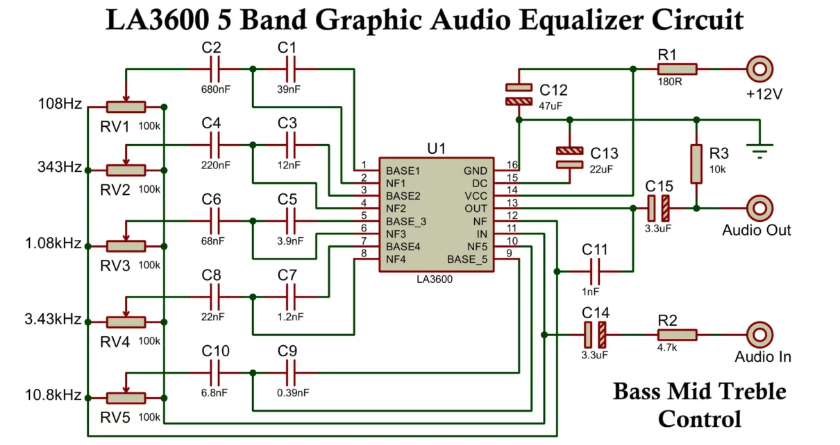
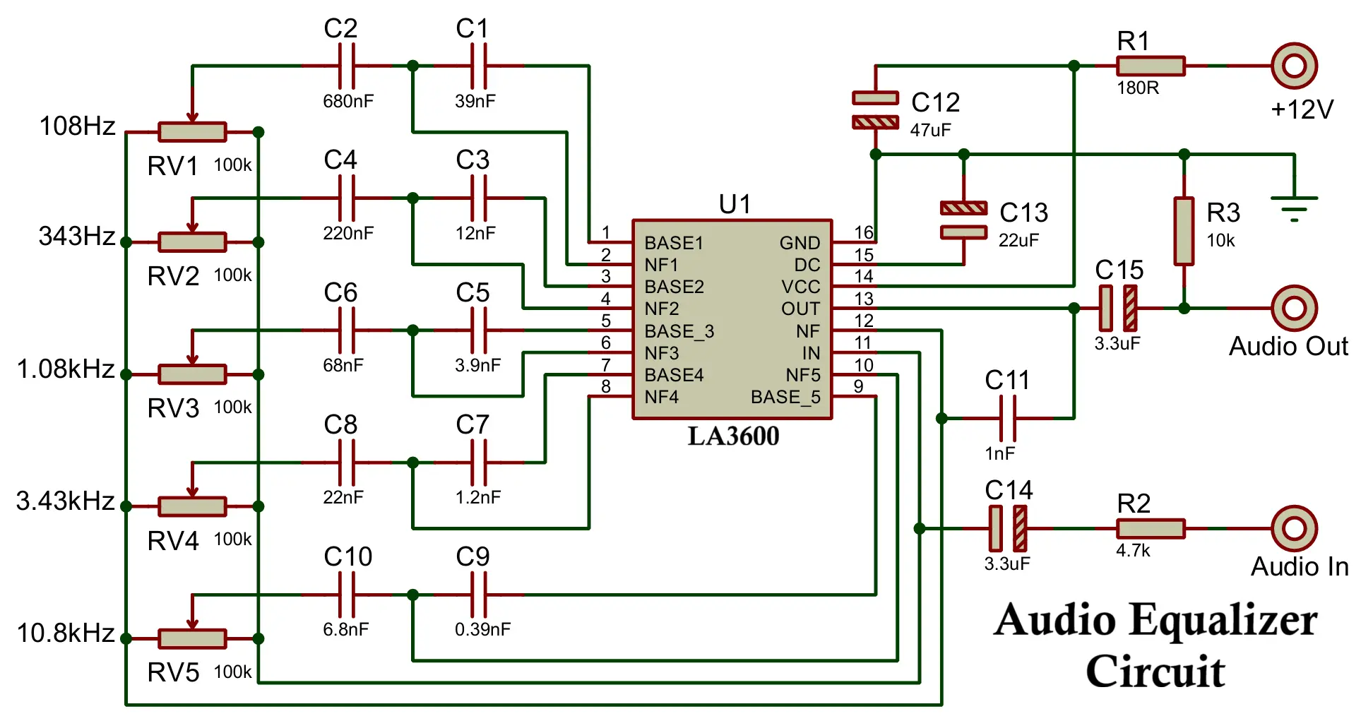
Circuit Diagram of LA3600 Audio Equalizer
This simple equalizer circuit uses LA3600 with a few external capacitors and resistors.
- The input audio signal is first passed through a buffer amplifier stage (internal to the IC).
- Then, the circuit distributes the signal into five band-pass filters, each tuned to a particular frequency range.
- It connects each band to a potentiometer (slider or rotary) that adjusts the gain (boost or cut).
- Finally, it mixes the outputs of all five bands to produce the final equalized audio output.
External Components Required:
- Integrated Circuit (IC): U1: LA3600,
- Fixed Resistors: R1: 180 Ω, R2: 4.7 kΩ, R3: 10 kΩ,
- Variable Resistors (Potentiometers): RV1: 100 kΩ (108 Hz), RV2: 100 kΩ (343 Hz), RV3: 100 kΩ (1.08 kHz), RV4: 100 kΩ (3.43 kHz), RV5: 100 kΩ (10.8 kHz),
- Capacitors: C1: 39 nF, C2: 680 nF, C3: 12 nF, C4: 220 nF, C5: 3.9 nF, C6: 68 nF, C7: 1.2 nF, C8: 22 nF, C9: 0.39 nF (390 pF), C10: 6.8 nF, C11: 1 nF, C12: 47 μF, C13: 22 μF, C14: 3.3 μF, C15: 3.3 μF,
- Connectors/Terminals: Power Input +12 V, Ground, Audio Input, Audio Output.
Capacitors (to set filter frequencies), Potentiometers (to adjust gain per band), Resistors (bias and stability settings). This makes the LA3600 extremely simple compared to designing a full multi-band equalizer using discrete op-amps.
Construction of LA3600 Audio Equalizer Circuit
- IC Placement – The LA3600 is a 16-pin IC, usually placed at the center of the equalizer board.
- Input Section – Audio input (from preamplifier or source) is connected to the input pin of the IC through a coupling capacitor.
- Filter Capacitors – Each band requires specific capacitors connected to corresponding pins of the IC. The values of these capacitors determine the cut-off frequencies.
- Potentiometers – Five potentiometers are connected externally, each controlling one frequency band. These can be mounted as sliders (in graphic equalizers) or rotary knobs.
- Output Section – The mixed and equalized audio signal is taken out through the output pin, which is then fed into the main amplifier stage.
- Power Supply – A regulated DC supply (commonly 12V) is connected to the IC. Proper decoupling capacitors are used to minimize noise.
In practical equalizers, the LA3600 is mounted on a PCB with all five potentiometers aligned in a row, allowing easy frequency adjustment by the user.
Working of LA3600 Audio Equalizer Circuit
The operation of the LA3600 is based on active band-pass filtering:
- Input Buffering – The incoming audio signal is buffered inside the IC to ensure minimal loading and impedance matching.
- Signal Distribution – The buffered signal is split into five paths. Each path contains an active band-pass filter tuned to a specific frequency band.
- Frequency Selection – The center frequency of each band-pass filter is determined by external capacitors connected to the IC. For example:
- Band 1: ~100 Hz (Bass)
- Band 2: ~300 Hz (Low midrange)
- Band 3: ~1 kHz (Midrange)
- Band 4: ~3 kHz (Upper midrange)
- Band 5: ~10 kHz (Treble)
- Gain Control – Each band output is connected to a potentiometer. By adjusting the potentiometer, the gain can be increased (boost) or decreased (cut) for that frequency band.
- Signal Mixing – After individual adjustments, the outputs of all five bands are summed together inside the IC.
- Final Output – The equalized signal is sent out to the power amplifier, where it drives speakers with improved tonal quality.
This allows users to customize bass, mid, and treble levels independently, providing flexibility in sound tuning.
Advantages
- Compact Design – Provides a complete five-band equalizer in a single IC.
- Simplified Circuitry – Requires fewer external components compared to discrete op-amp designs.
- Low Noise and Distortion – Ensures high-quality sound output.
- User-Friendly Control – Easy to integrate with slider or rotary potentiometers for real-time adjustment.
- Wide Supply Voltage Range – Compatible with both home and car audio systems.
- Reliable Performance – Proven IC used in many commercial equalizer designs.
Disadvantages
- Limited Bands – Only five frequency bands are available, while professional equalizers may offer 7, 10, or 15 bands.
- Fixed Frequencies – Center frequencies are determined by capacitor values and cannot be dynamically adjusted without redesigning the circuit.
- Outdated Availability – The LA3600 is an older IC and may be harder to source in modern markets.
- Not Suitable for Digital Audio – Designed for analog audio processing only.
Applications
The LA3600 audio equalizer circuit is commonly used in a variety of audio systems, including:
- Home Stereo Systems – For enhancing bass, treble, and midrange response.
- Car Audio Systems – To adjust sound according to car cabin acoustics.
- Portable Audio Devices – Equalization in boomboxes and mini-systems.
- DIY Audio Projects – Widely used by hobbyists for building graphic equalizers.
- Public Address (PA) Systems – To improve speech clarity and music quality.
- Music Mixing Consoles (basic versions) – For tone shaping in small audio setups.
Conclusion
The LA3600 audio equalizer IC provides a simple yet effective solution for building a five-band graphic equalizer. Its construction is straightforward, requiring only external capacitors and potentiometers, while its working principle relies on active band-pass filtering. Although it has limitations such as fixed frequency bands and fewer adjustments compared to modern equalizers, it remains an excellent choice for hobbyists and entry-level audio systems.
You can use the LA3600 audio equalizer with TDA2030 audio amplifier circuit by connecting the equalizer first, then sending its output to the amplifier. The equalizer lets you adjust bass, mid, and treble, and the TDA2030 amplifies the sound to drive speakers, giving better tone and volume.
By using the LA3600, audio enthusiasts can easily enhance sound quality, tailor audio to personal preferences, and build compact equalizer systems without complex circuitry.
TDA2030 Audio Amplifier Circuit: Mono, Stereo and Bass Amplifier
Digital to Analog Converter (DAC) Block Diagram, Working, Types & Applications
Analog to Digital Converter (ADC) Block Diagram, Working, Types & Applications
