An Asynchronous Counter, also known as a Ripple Counter, is a type of digital counter where the clock signal is applied to only the first flip-flop, and subsequent flip-flops toggle based on the output of the previous one. This introduces a propagation delay, making it “asynchronous.”
Asynchronous Binary Counter Terminology
Here’s a breakdown of all the key terminologies related to Asynchronous Counters:
Basic Concepts
- Clock Pulse – A periodic signal that synchronizes changes in flip flops. In an asynchronous counter, only the first flip-flop receives the clock directly.
- Flip-Flop – A bistable circuit used as a memory element in counters. Common types include:
- JK Flip-Flop
- D Flip-Flop
- T Flip-Flop (commonly used in ripple counters)
- Binary Counter – A counter that counts in binary sequence (0, 1, 10, 11, etc.).
Counter Types
- Synchronous Counter – A counter where flip-flops are triggered simultaneously by a common clock signal, eliminating the propagation delay issues found in asynchronous counters.
- Asynchronous Counter (Ripple Counter) – A counter where flip-flops are not clocked simultaneously but toggle in sequence, leading to propagation delay.
- Up Counter – A counter that increments its count on each clock pulse (e.g., 0000 → 0001 → 0010 → …).
- Down Counter – A counter that decrements its count on each clock pulse (e.g., 1111 → 1110 → 1101 → …).
- Up/Down Counter – A counter that can operate in both counting directions, controlled by a mode input.
- Decade Counter – A counter with MOD-10 (counts 0 to 9 and then resets to 0).
- Ring Counter – A shift register counter where only one flip-flop is set (1) at a time, and the bit circulates.
- Johnson Counter (Twisted Ring Counter) – A counter where the inverted output of the last flip-flop is fed back to the first, creating a different counting sequence.
- Truncated Counter – A counter that does not use all possible states of its flip-flops.
- Example: A MOD-6 counter using 3 flip-flops (which could count up to MOD-8) but resets at 6.
Counter Properties
- Modulus (MOD) of a Counter – The number of unique states a counter cycles through before repeating.
- Example: A 4-bit counter has a MOD of 16 (counts from 0000 to 1111).
- Terminal Count (TC) – The last state of a counter before it resets or overflows.
- Example: A 4-bit up-counter reaches 1111 (15 in decimal) as its terminal count.
- Overflow & Underflow
- Overflow – When the counter exceeds its maximum state and resets (e.g., 1111 → 0000).
- Underflow – When a down-counter goes below its minimum state (0000) and wraps around.
Timing & Performance Issues
- Propagation Delay – The time taken for a change in input to reflect in the output of a flip-flop. Delays accumulate in an asynchronous counter.
- Clock Skew – The difference in arrival time of the clock signal at different flip-flops, causing timing issues in large circuits.
- Race Condition – A condition where the delay between flip-flops causes unexpected behavior due to timing issues.
- Glitch – A brief, unintended fluctuation in output due to propagation delay.
- Frequency Division – Since each flip-flop toggles at half the frequency of the previous one, ripple counters can be used to divide input clock frequency.
Control & Operation
- Reset (Clear) – A control input used to force the counter back to zero.
- Preset (Load) – A control input that sets the counter to a specific value instead of resetting to zero.
- Synchronous vs. Asynchronous Counter
- Synchronous Counter – All flip-flops receive the clock signal simultaneously.
- Asynchronous Counter – Flip-flops toggle sequentially based on the output of the previous one.
Advanced Concepts
- Cascading Counters – Connecting multiple counters together to extend the counting range.
- Example: Two 4-bit counters combined to form an 8-bit counter (MOD-256).
- Power Consumption – Asynchronous counters consume less power than synchronous counters due to fewer simultaneous switching events.
- Application-Specific Counters – Used in applications like:
- Frequency dividers
- Event counters
- Digital clocks
- Timers
- Frequency meters
Difference Between Asynchronous and Synchronous Counters
| Feature | Asynchronous Counter | Synchronous Counter |
|---|---|---|
| Clocking | Different clocks | Same clock |
| Propagation Delay | High | Low |
| Speed | Slow | Fast |
| Glitches | Possible | Minimized |
Asynchronous Counters Using JK Flip-Flops
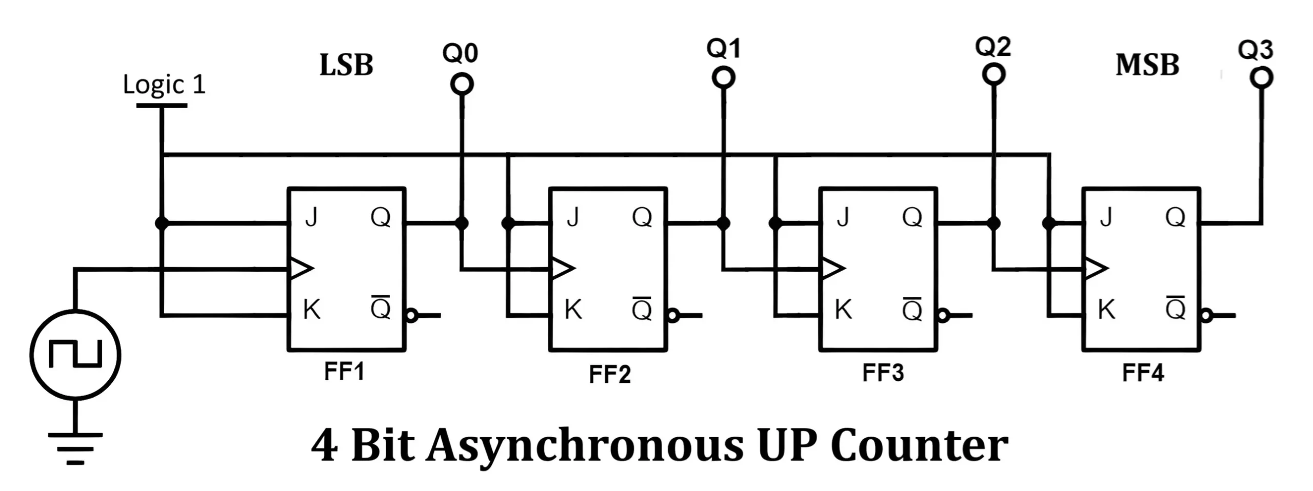
A. 4-Bit Asynchronous Up Counter Using JK Flip-Flops
A 4-bit asynchronous up counter consists of four JK flip-flops (FF0 to FF3) connected in a cascading manner, where the output of one flip-flop acts as the clock input for the next flip-flop.
Circuit Design
- The first flip-flop (FF0) receives the external clock signal.
- The output of each flip-flop toggles when the preceding flip-flop transitions from HIGH (1) to LOW (0).
- Each flip-flop’s J and K inputs are set to HIGH (1) for toggling.
- The output (Q0 to Q3) represents a binary count, with FF0 as the Least Significant Bit (LSB) and FF3 as the Most Significant Bit (MSB).
Circuit Diagram
Truth Table
| Clock Pulse | Q3 | Q2 | Q1 | Q0 |
|---|---|---|---|---|
| 0 | 0 | 0 | 0 | 0 |
| 1 | 0 | 0 | 0 | 1 |
| 2 | 0 | 0 | 1 | 0 |
| 3 | 0 | 0 | 1 | 1 |
| … | … | … | … | … |
| 15 | 1 | 1 | 1 | 1 |
| 16 (Clear) | 0 | 0 | 0 | 0 |
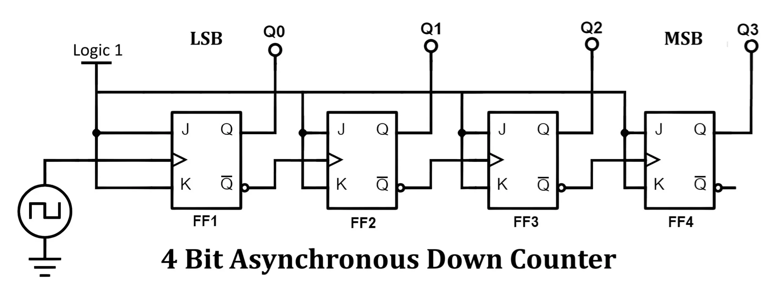
B. 4-Bit Asynchronous Down Counter Using JK Flip-Flops
A 4-bit asynchronous down counter functions similarly to the up counter but counts in the reverse order (from 1111 to 0000). Instead of toggling on HIGH-to-LOW transitions, each flip-flop toggles when the previous flip-flop transitions from LOW (0) to HIGH (1).
Circuit Design
- The first flip-flop (FF0) still receives the clock input.
- The subsequent flip-flops toggle when the preceding flip-flop shifts from LOW to HIGH.
- The J and K inputs are set to HIGH (1) to enable toggling.
Circuit Diagram
Truth Table
| Clock Pulse | Q3 | Q2 | Q1 | Q0 |
|---|---|---|---|---|
| 0 | 1 | 1 | 1 | 1 |
| 1 | 1 | 1 | 1 | 0 |
| 2 | 1 | 1 | 0 | 1 |
| 3 | 1 | 1 | 0 | 0 |
| … | … | … | … | … |
| 15 | 0 | 0 | 0 | 0 |
| 16 (Reset) | 1 | 1 | 1 | 1 |
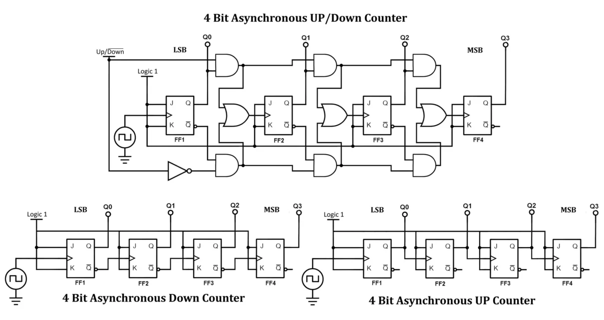
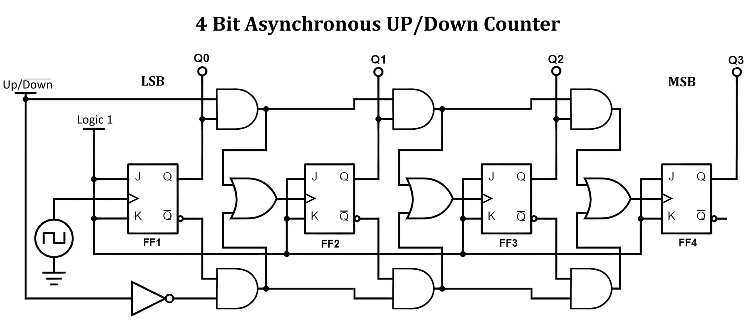
C. 4-Bit Asynchronous Up/Down Counter Using JK Flip-Flop
A 4-bit asynchronous up down counter allows counting in both ascending and descending order using a control input. IC 74193 is a popular 4 bit binary up and down counter. See datasheet of IC 74193.
Circuit Design
- The counter includes four JK flip-flops (FF0 to FF3).
- A control signal (UP/DOWN) determines the counting direction.
- Additional AND, OR, and NOT gates control the toggling of flip-flops based on the UP/DOWN input.
Circuit Diagram
Truth Table
| Clock Pulse | UP/DOWN | Q3 | Q2 | Q1 | Q0 |
|---|---|---|---|---|---|
| 0 | 1 (UP) | 0 | 0 | 0 | 0 |
| 1 | 1 (UP) | 0 | 0 | 0 | 1 |
| 2 | 1 (UP) | 0 | 0 | 1 | 0 |
| … | … | … | … | … | … |
| 15 | 1 (UP) | 1 | 1 | 1 | 1 |
| 16 | 0 (DOWN) | 1 | 1 | 1 | 0 |
| 17 | 0 (DOWN) | 1 | 1 | 0 | 1 |
| … | … | … | … | … | … |
| 31 | 0 (DOWN) | 0 | 0 | 0 | 0 |
Working of 4-bit Asynchronous Counters
Up Counter Operation
- FF0 toggles on each clock pulse.
- FF1 toggles when FF0 transitions from HIGH to LOW.
- FF2 toggles when FF1 transitions from HIGH to LOW.
- FF3 toggles when FF2 transitions from HIGH to LOW.
- The count progresses from 0000 to 1111 (decimal 0 to 15).
Down Counter Operation
- FF0 toggles on each clock pulse.
- FF1 toggles when FF0 transitions from LOW to HIGH.
- FF2 toggles when FF1 transitions from LOW to HIGH.
- FF3 toggles when FF2 transitions from LOW to HIGH.
- The count decreases from 1111 to 0000 (decimal 15 to 0).
Up/Down Counter Operation
- When UP/DOWN = 1, the counter functions as an up counter.
- FF0 toggles on each clock pulse.
- Each subsequent flip-flop toggles when the previous one transitions from 1 to 0.
- Binary sequence:
000 → 001 → 010 → 011 → 100 → 101 → 110 → 111 → 000
- When UP/DOWN = 0, the counter functions as a down counter.
- FF0 still toggles on every clock pulse.
- Each subsequent flip-flop toggles when the previous one transitions from 0 to 1.
- Binary sequence:
000 → 111 → 110 → 101 → 100 → 011 → 010 → 001 → 000
Flip-flops toggle based on the previous flip-flop’s state and the control input.
Timing Diagram of 4 Bit Asynchronous Counters
A timing diagram represents the changes in flip-flop outputs over time concerning the clock pulses. Since asynchronous counters operate in a ripple effect (each flip-flop is triggered by the previous flip-flop’s output instead of a common clock), a propagation delay exists between state transitions. This causes the outputs to change at slightly different times.
Timing Diagram of 4-Bit Asynchronous Up Counter
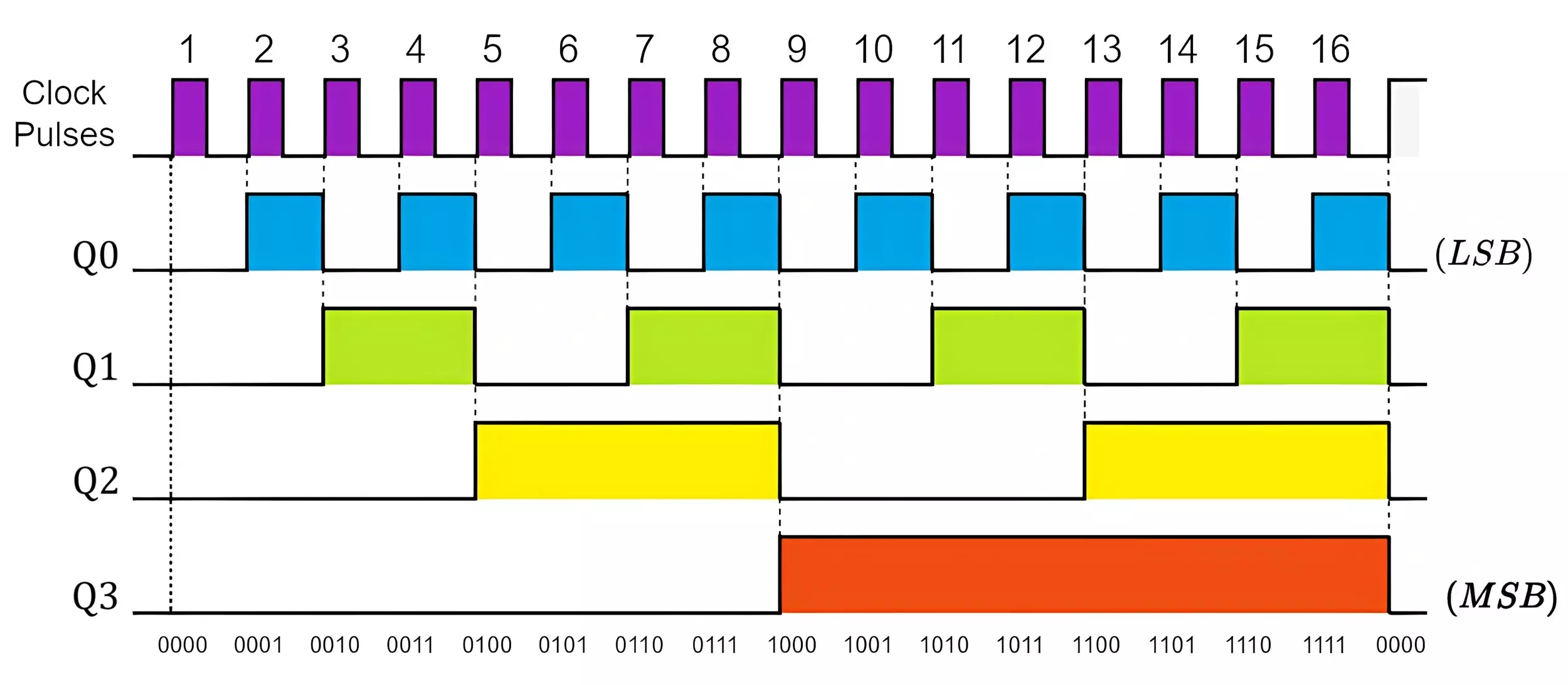
Observations
Each flip-flop lags behind the previous flip-flop due to the ripple effect.
Q0 toggles first, followed by Q1, Q2, and finally Q3.
The counter increases from 0000 to 1111 (decimal 0 to 15).
Timing Diagram of a 4-Bit Asynchronous Down Counter
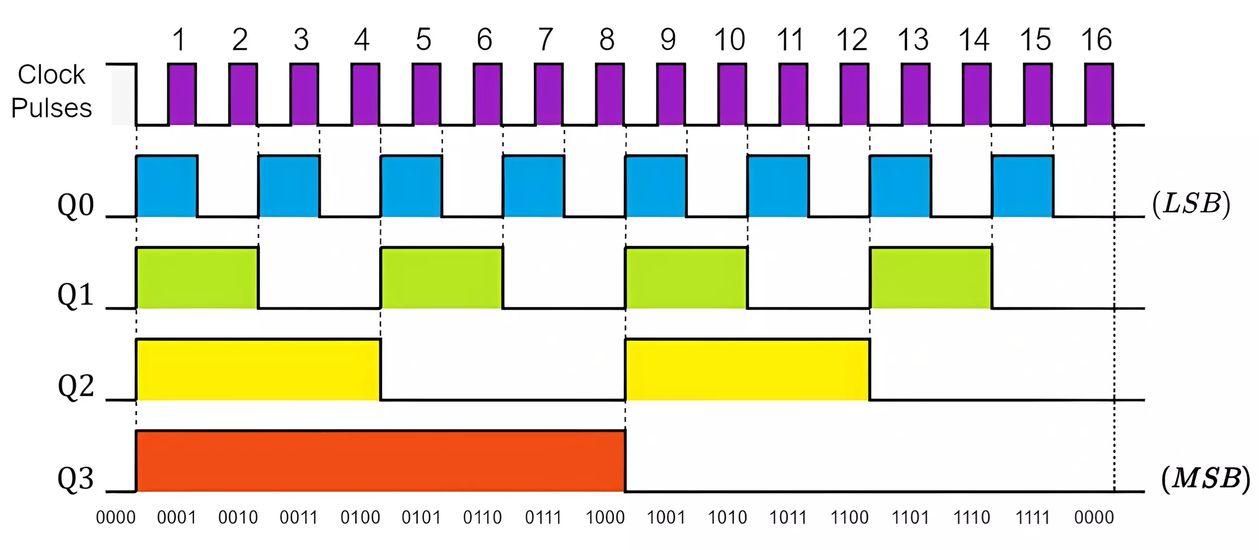
Observations
The waveform is similar to the up counter but reversed in order.
Q0 toggles first, followed by Q1, Q2, and then Q3.
The counter decreases from 1111 to 0000 (decimal 15 to 0).
4-Bit Asynchronous Up/Down Counter
- When UP/DOWN = 1, the counter behaves as an up counter and follows the up-counter waveform.
- When UP/DOWN = 0, the counter behaves as a down counter and follows the down counter waveform.
- The control signal determines whether the counter increments or decrements.
- The transition between UP and DOWN introduces a small delay due to the ripple effect.
Timing Diagram Differences
- Asynchronous Up Counter: The counter increases its count on each clock pulse.
- Asynchronous Down Counter: The counter decreases its count on each clock pulse.
- In an up counter, the least significant bit (LSB) toggles at every clock pulse, and the higher bits toggle when the previous bit transitions from 1 to 0.
- In a down counter, the LSB still toggles at every clock pulse, but higher bits toggle when the previous bit transitions from 0 to 1.
Transition of Flip-Flops
- FF0 always toggles with the clock, but the edge type (rising/falling) depends on the flip-flop type.
- Up Counter: Higher FFs toggle on the falling edge of the previous FF.
- Down Counter: Higher FFs toggle on the rising edge of the previous FF.
- The first FF behaves identically in up and down counters—the counting direction is determined by the higher FFs.
✅ Advantages of Asynchronous Counters
- Simple Design – Requires fewer components since each flip-flop is triggered by the previous one, not a common clock.
- Easy to Construct – Uses standard T or JK flip-flops with minimal wiring.
- Low Power Consumption – Fewer simultaneous switching events reduce power usage.
- Requires No Additional Clocking Circuit – Since only the first flip-flop receives the external clock.
❌ Disadvantages of Asynchronous Counters
- Propagation Delay (Ripple Effect) – Each flip-flop must wait for the previous one to toggle, causing timing issues.
- Not Suitable for High-Speed Operations – Delays accumulate, making it unsuitable for high-frequency applications.
- Glitches and Race Conditions – Since all flip-flops don’t change state simultaneously, errors can occur in fast-changing inputs.
- Difficult to Implement Synchronous Control – Hard to reset or modify counting sequences without affecting timing.
🔹 Applications of Asynchronous Counters
- Frequency Dividers – Used in digital clocks and radio circuits.
- Time Delays – Used in delay circuits where precision timing isn’t critical.
- Event Counting – Used in digital counters, tally systems, and stepper motor controllers.
- LED Chasers & Pattern Generators – Used in display circuits.
- Simple Low-Speed Counters – Used in inexpensive digital devices where timing accuracy isn’t a concern.
Conclusion
A 4-bit asynchronous counter is a simple way to count from 0000 to 1111 using flip-flops. Each flip-flop gets its clock from the previous one, creating a ripple effect that causes delays. While this makes them slower than synchronous counters, they are easy to build and useful for frequency division, digital clocks, and event counting. For high-speed applications, synchronous counters are better, but for basic counting tasks, asynchronous counters are a good choice. You can make a binary up and down counter using
JK Flip Flop Truth Table, Circuit Diagram, Working & Applications
