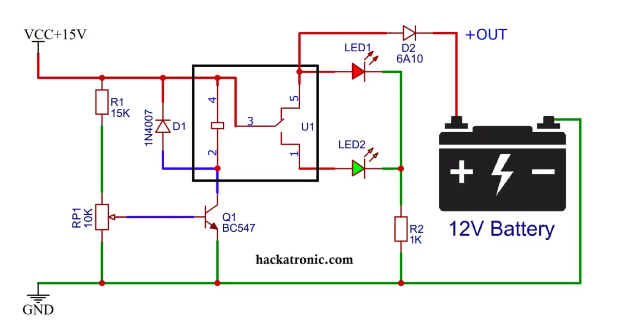
This article details the construction and working of an Automatic Cut-Off Battery Charger Circuit using common components such as a relay, transistor, potentiometer (pot), LED, diodes, and resistors. Battery chargers with automatic cut-off functionality ensure batteries do not overcharge, enhancing their life span and performance. This circuit charges the battery in its Normally Closed (NC) state and once fully charged it disconnects to Normally Open (NO) state. You can also see a simple battery charger circuit using MOSFET.
Components Required for Battery Charger:
- Relay: 12V, SPDT (Single Pole Double Throw) relay.
- Transistor: NPN transistor (e.g., BC547).
- Potentiometer (Pot): 10kΩ for voltage adjustment.
- LED: Red (charging indicator) and Green (cut-off indicator).
- Diodes: 1N4007, 6A10 (for protection).
- Resistors: 15kΩ, and 1kΩ current-limiting resistor for LEDs.
- Power Supply: 15V DC from transformer or SMPS power supply (nearly 14V).
- Battery: Lead-acid or lithium-ion battery (12V in this example).
Circuit Diagram and Connections:
1. Relay Connections:
- Connect the NC (Normally Closed) terminal of the relay to the Red LED and positive terminal of the battery.
- The NO (Normally Open) terminal connects to the Green LED that turns on when charging is complete.
- The Common (COM) and relay coil terminals connects to the positive terminal of the power supply.
2. Transistor Stage:
- The collector of the NPN transistor (BC547) connects to one side of the relay coil.
- The emitter connects to the ground.
- A flyback diode (1N4007) is connected across the relay coil to protect the transistor from voltage spikes.
3. Voltage Sensing and Control:
- The base of the transistor is connected to a 10kΩ potentiometer making a voltage divider network.
- The potentiometer is used to set the cut-off voltage threshold. Also, there is a 15kΩ fixed resistor.
- The voltage divider taps into the battery’s voltage and feeds it to the transistor’s base for control.
4. Indication Circuit:
- A red LED (charging indicator) is connected to NC terminal to indicate charging.
- A green LED (cut-off indicator) is connected to the NO terminal to indicate charging completion. A 1kΩ current-limiting resistor is used to limit the current.

Working of Automatic Cut Off Battery Charger Circuit:
1. Charging Mode:
When the circuit is powered, and the battery voltage is below the set threshold:
-
- The relay remains in the NC position, allowing current to flow from the power supply to the battery.
- The red LED lights up, indicating the battery is charging.
2. Cut-Off Mode:
As the battery reaches the pre-set voltage threshold (adjustable using the potentiometer):
-
- The voltage at the transistor’s base increases, turning it on.
- This energizes the relay coil, switching it from NC to NO, cutting off the charging current to the battery.
- The green LED turns on, indicating charging is complete.
3. Protection Mechanism:
- The diode across the relay coil (flyback diode) protects the transistor from back EMF.
- Additional diodes prevent reverse polarity damage to the circuit.
Key Advantages of This Circuit:
- Automatic Control: Prevents overcharging, improving battery life and safety.
- Adjustable Cut-Off: The potentiometer allows fine-tuning of the cut-off voltage.
- Indication: LEDs provide visual feedback on charging status.
Calibration and Testing:
Set Cut-Off Voltage:
- Connect the battery and power supply.
- Adjust the potentiometer while monitoring the battery voltage. Set the potentiometer to trigger the relay at the desired voltage.
Observe Indications:
Check the LEDs to ensure they switch correctly between charging (red LED) and cut-off (green LED) states.
Watch this video for better understanding.
Conclusion:
This simple yet effective Automatic Cut-Off Battery Charger Circuit provides a reliable way to manage battery charging without manual intervention. The use of a relay, transistor, potentiometer, and LEDs ensure precise control and status indication. With proper calibration, this circuit can be used for various battery types, making it a valuable tool for hobbyists and professionals.


Hello ! Thanks for your job !
How to build and calculate the same schema, with one more transistor, in darlington stage ?
(just for fun)
Thanks by advance
What is the use of darlington stage here!?
Circuit is fine.