Flyback and forward converters are two of the most commonly used topologies in switch-mode power supplies (SMPS). Although they both function as isolated DC-DC converters, they differ in their operation, design, and applications. Here’s a comparison flyback converter vs forward converter.
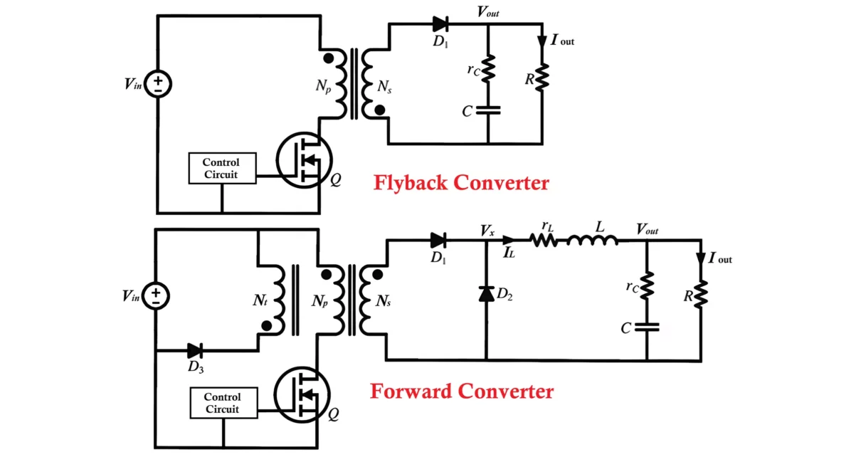
Flyback Converter Circuit:
A flyback converter is a type of DC-DC converter commonly used in low-power applications, such as power supplies for televisions, battery chargers, and LED drivers. The primary function is to convert an unregulated DC input voltage into a regulated DC output voltage.
Working Principle:
The flyback converter works on the principle of energy storage and release. It operates in two main modes: switch ON (energy storage) and switch OFF (energy release).

Switch ON (Energy Storage Mode):
- When the switch (typically a MOSFET or transistor) is turned on, current flows through the primary winding of the transformer.
- During this phase, energy is stored in the magnetic core of the transformer in the form of a magnetic field.
- Importantly, in a flyback converter, the transformer doesn’t transfer energy directly to the output during this phase.
- The polarity of the induced voltage in the secondary winding opposes the output current flow, so no current flows through the output.
Switch OFF (Energy Release Mode):
-
- When the switch is turned off, the magnetic field in the transformer collapses.
- This collapse induces a voltage in the secondary winding of the transformer, but the polarity now reverses, allowing current to flow to the output.
- The stored energy in the transformer is transferred to the load via the output diode and is filtered by an output capacitor to provide a stable DC output.
Advantages:
- Galvanic isolation between input and output.
- Suitable for multiple output voltages.
- Simplified transformer design since no continuous energy transfer.
Disadvantages:
- Voltage and current stress on components, especially the switch.
- Not as efficient as some other topologies for higher power levels.
Forward Converter Circuit:
A forward converter is another type of isolated DC-DC converter used for regulated power supplies in applications such as telecommunication systems, industrial controls, and battery chargers. It directly transfers energy from input to output during the switch’s ON state.
Working Principle:
The forward converter works by directly transferring energy from the primary to the secondary winding of the transformer during the switch ON state.

Switch ON (Energy Transfer Mode):
- When the switch is turned on, current flows through the primary winding of the transformer.
- This induces a voltage in the secondary winding, and the diode becomes forward-biased, allowing current to flow to the load and charge the output capacitor.
- Energy is simultaneously delivered to the load and stored in the output capacitor to maintain voltage stability when the switch turns off.
- A reset mechanism for the transformer (via a tertiary winding or an additional demagnetizing winding) is required to avoid core saturation.
Switch OFF (Freewheeling Mode):
- When the switch is turned off, the energy stored in the output inductor (if used) and capacitor provides current to the load.
- During this phase, the freewheeling diode provides a path for the current, ensuring continuous energy flow to the load.
Advantages:
- Direct energy transfer results in higher efficiency than a flyback converter, especially at higher power levels.
- Reduced voltage and current stress on the components compared to flyback.
- Better suited for medium to high power applications.
Disadvantages:
- More complex due to the need for a reset mechanism for the transformer to prevent saturation.
- Requires an output inductor to maintain current flow when the switch is off.
Transformer and Core Utilization:
Flyback Converter:
-
- The flyback transformer functions like an inductor. During the on-time, the core stores energy, and during the off-time, this energy is released.
- It can be used in both continuous and discontinuous conduction modes depending on design.
- Since the transformer only transfers energy during off-time, the flyback transformer does not require core resetting.
Forward Converter:
-
- The forward converter’s transformer transfers energy during the on-time, and requires a reset mechanism (like a reset winding or clamp circuit) to avoid core saturation during off-time.
- More efficient core utilization because energy transfer occurs directly while the switch is on.
Energy Transfer Mode:
Flyback Converter:
-
- Operates in discontinuous energy transfer mode. Energy is transferred to the output only during the off-time of the switch.
- This often leads to higher peak currents and requires larger filtering components to smooth the output.
Forward Converter:
-
- Operates in continuous energy transfer mode. Energy is transferred during the switch on-time directly, leading to lower peak currents.
- This typically results in smoother current flow and can lead to more efficient energy transfer, especially for higher power applications.
Number of Components:
Key Components:
- Transformer: Used for energy transfer and provides galvanic isolation.
- Switching Element: A MOSFET or transistor that controls the power flow.
- Diode: Allows current to flow to the output during the ON phase.
- Capacitor: Smooths the output voltage.
- Freewheeling Diode: Provides continuity of current when the switch is off.
Flyback Converter:
-
- Simpler design with fewer components (e.g., no need for a reset winding or clamp circuit).
- Only requires a single winding on the secondary side.
- Suitable for low-to-medium power applications.
Forward Converter:
-
- More complex due to the need for a reset mechanism (reset winding or clamp circuit) and the additional filter inductor on the output side.
- Requires additional components like an output inductor and possibly a clamp circuit.
- Better suited for higher power levels and more demanding applications.
Output Power Capability:
Flyback Converter:
-
- Typically used in low to medium power applications (up to ~150W, although can go higher with optimized designs).
- Best for low-cost designs where simplicity is important, such as chargers and small power supplies.
Forward Converter:
-
- Capable of handling higher power levels (up to several hundred watts or more).
- Suitable for applications requiring higher efficiency and better regulation.
Efficiency:
Flyback Converter:
-
- Generally, the flyback converter is less efficient due to the energy storage and higher peak currents.
- Efficiency is usually around 70-85%, though modern designs can improve this slightly.
Forward Converter:
-
- Typically more efficient due to continuous energy transfer and lower ripple currents.
- Efficiency can be 85-95%, especially in well-designed systems.
Applications:
Flyback Converter:
-
- Ideal for low-to-medium power and low-cost designs.
- Common in wall adapters, battery chargers, and standby power supplies.
- Suitable for designs with wide output voltage ranges and multiple isolated outputs.
Forward Converter:
-
- Typically used in higher power applications and where efficiency and regulation are more critical.
- Found in industrial power supplies, telecom equipment, and higher power DC-DC converters.
Design Complexity:
Flyback Converter:
-
- Easier to design and less complex due to fewer components.
- It does not need a core reset winding or a clamp circuit, which simplifies the design.
Forward Converter:
-
- More complex due to the need for additional components, such as an output inductor, a reset winding, or a clamp circuit to reset the core.

Difference Between Flyback converter and Forward converter:
| Feature | Flyback Converter | Forward Converter |
|---|---|---|
| Energy Transfer | Stored in transformer core (off-time) | Direct during on-time |
| Conduction Mode | Discontinuous or continuous | Continuous |
| Transformer Role | Acts as both transformer and inductor | Acts purely as transformer |
| Core Reset | Not required | Required (via reset winding or clamp) |
| Power Capability | Low to medium (up to ~150W) | Medium to high (hundreds of watts) |
| Efficiency | Moderate (70-85%) | Higher (85-95%) |
| Design Complexity | Simple | More complex |
| Application Examples | Chargers, small power supplies | Industrial power, telecom systems |
Conclusion Flyback Converter vs Forward Converter:
- Flyback converters are preferred for low to medium power applications, especially where cost and simplicity are important.
- Forward converters are used for higher power and efficiency-demanding applications due to their continuous energy transfer and better regulation.
