In this article, we’ll explore the SPWM inverter block diagram, its operation and break down the components in detail to understand the working.
Inverter systems are critical in various applications, including renewable energy systems, solar power systems, electric motor drives, backup power supplies, and uninterruptible power supplies (UPS). A well-designed inverter system ensures seamless transition between power sources and reliable performance. This article delves into the block diagram of an inverter system featuring an AC input, a Switch Mode Power Supply (SMPS) battery charging section, a Sinusoidal Pulse Width Modulation (SPWM) inverter section, and a relay changeover section.
Sinusoidal Pulse Width Modulation (SPWM) is a widely used technique for generating high-quality sinusoidal waveforms in inverter circuits. The SPWM inverter circuit provides a reliable and efficient way to generate AC from DC with minimized harmonic distortion, making it ideal for sensitive and inductive loads.
What is an SPWM Inverter?
An SPWM inverter is an electronic circuit that converts DC (Direct Current) into AC (Alternating Current) using Sinusoidal Pulse Width Modulation. SPWM modulates the width of the pulses in a manner that corresponds to a sinusoidal waveform. This technique ensures that the output AC waveform resembles a pure sine wave with reduced harmonic distortion, improving the performance and efficiency of AC-powered devices.
Why Use SPWM?
Traditional square wave inverters generate high harmonic distortion and are not ideal for devices that require a pure sinusoidal wave. Modified sine wave inverters offer some improvement, but SPWM inverters are superior in the following ways:
- Lower Harmonic Distortion: SPWM minimizes unwanted harmonic frequencies, reducing heat generation in connected devices.
- Higher Efficiency: Since the switching devices (MOSFETs or IGBTs) operate in the on/off mode, switching losses are reduced.
- Stable Voltage and Frequency: SPWM inverters can regulate the output voltage and frequency effectively, making them suitable for applications like renewable energy systems.
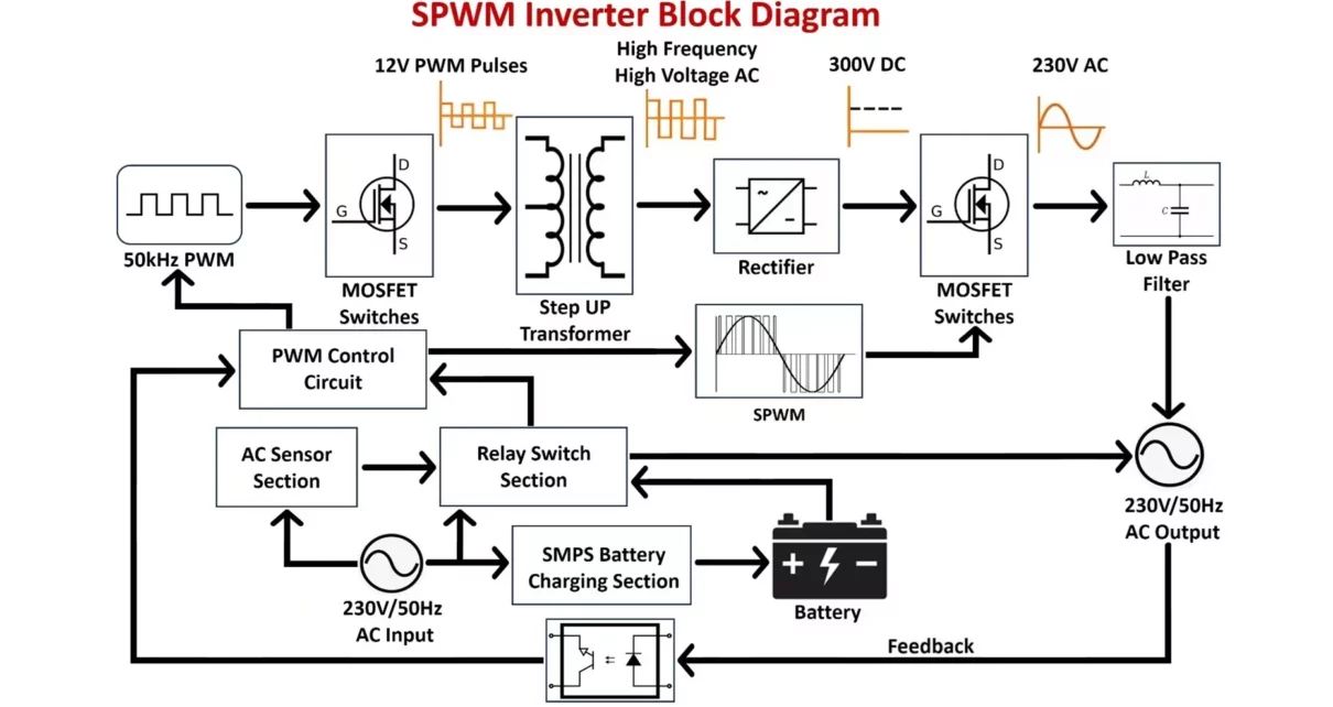
SPWM Inverter Block Diagram Explained:
Here’s a breakdown of the SPWM inverter block diagram, highlighting the essential functional blocks and their operation:
1. AC Input Section
The AC input section is the primary source of power for the inverter system when the main grid (mains supply) is available. It comprises:
- AC Mains Input: This is the connection point for the utility power supply, typically providing 230V AC at 50Hz. It powers the inverter system and charges the battery during normal operation.
- AC Sensor Circuit: The AC sensor circuit detects whether the AC mains are available or not. If the AC mains is present, the sensor triggers the relay section to switch the system into charging mode. If the mains are absent, it switches to inverter mode.
- AC Filter: Used to filter out noise and harmonics from the AC supply to ensure smooth operation of the inverter.
- Protection Circuit: Includes fuses or circuit breakers to protect the system from overloads and short circuits.
2. SMPS Battery Charging Section
The Switch Mode Power Supply (SMPS) is responsible for charging the inverter’s battery when AC mains are available. This section includes:
- AC-DC Converter: The input AC voltage is converted to a stable DC voltage using an AC-DC converter. The converter consists of a step-down transformer, rectifier, and filter. The transformer steps down the high mains voltage to a lower level, and the rectifier converts it to DC, followed by filtering to smooth out any ripples.
- Battery Charger Circuit: The charger regulates the current and voltage supplied to the battery, ensuring safe and efficient charging. This section adjusts the charge rate according to the battery’s capacity and state of charge.
- Battery: The battery stores electrical energy for use when the AC mains is unavailable. Typically, a 12V lead-acid or lithium-ion battery is used, depending on the application.
- Battery Management System (BMS): Monitors and manages the battery’s state of charge, health, and temperature. It ensures optimal performance and longevity of the battery.
When the mains power is present, the SMPS charges the battery, and the inverter remains in standby mode. Once the mains power fails, the system switches to inverter mode via the relay changeover section.
3. Relay Changeover Section
The relay changeover section is responsible for switching between inverter and charging modes based on the availability of AC mains.
- Relay: The relay acts as a switch that connects the AC mains to output and battery charger or switches the system to inverter mode. It is triggered by the AC sensor circuit, which detects whether mains power is present.
- Control Circuit: A control logic circuit governs the relay operation based on signals from the AC sensor. If AC mains are detected, the relay switches to charging mode; if not, the system moves to inverter mode.

4. SPWM Inverter Section
The Sinusoidal Pulse Width Modulation (SPWM) inverter section is crucial for converting the stored DC voltage from the battery into an AC voltage that can power electrical loads.
- PWM Control Circuit: When the system switches to inverter mode, the PWM control circuit generates a 50 to 100kHz high-frequency PWM signal. This high-frequency PWM drives the MOSFET switches in the initial DC-AC conversion stage. Additionally, the control circuit generates a 50Hz SPWM signal to modulate the output and create a clean sinusoidal waveform.
- MOSFET Switching Stage: The 12V DC from the battery is used to drive the MOSFET switches. These switches, controlled by the PWM signals, convert the low-voltage DC into a high-frequency AC waveform.
- Step-Up Transformer: The 50kHz PWM-controlled MOSFET switches provide pulses to a step-up transformer. This transformer steps up the 12V AC pulses to approximately 230V AC at a high frequency of 50kHz. This high voltage is required for the subsequent stages of the inverter.
- Output Filter: Smooths the output waveform to reduce harmonics and produce a clean sine wave. This filter typically consists of inductors and capacitors.
- Heat Sink: Dissipates heat generated by the inverter components to maintain optimal operating temperatures and prevent overheating.
5. High-Frequency Rectification Section
Once the 12V DC has been converted into 230V AC at 50kHz, the next step is rectification and smoothing:
- Bridge Rectifier: The high-frequency AC voltage generated by the transformer is passed through a bridge rectifier. This rectifier converts the high-frequency AC into a stable 300V DC.
- Filter Circuit: A filter (typically composed of capacitors and inductors) is used to remove high-frequency noise from the rectified output, producing smooth DC voltage suitable for conversion into AC.
6. Low-Frequency SPWM Inverter Section
The next step involves converting the high DC voltage back into low-frequency AC for general use:
- 50Hz SPWM Signal: The PWM control circuit generates a low-frequency SPWM signal at 50Hz to control the MOSFET switches in the final inversion stage. This ensures that the output AC waveform is sinusoidal in shape.
- Final MOSFET Stage: The high-voltage DC is fed to another set of MOSFET switches that are modulated by the 50Hz SPWM signal. The output of these MOSFETs is a 50Hz AC voltage, though it still contains some high-frequency harmonics.
7. LC Low-Pass Filter
After the MOSFET stage, the AC voltage contains some high-frequency noise, which needs to be filtered out to produce a pure sinewave output. This is achieved using an LC low-pass filter.
- LC Filter: The LC filter consists of an inductor (L) and a capacitor (C) that together smooth out the waveform by attenuating the high-frequency components, allowing only the 50Hz fundamental frequency to pass through. The result is a clean 230V AC at 50Hz, suitable for powering household or industrial loads.
8. Feedback Circuit and Regulation
To maintain a stable 230V AC output, an optoisolator-based feedback circuit is employed.
- Optoisolator Feedback Circuit: This circuit senses the output voltage and provides an optically isolated feedback signal to the PWM control circuit. The optoisolator ensures that the feedback is electrically isolated from the high-voltage sections of the inverter, improving safety and system reliability.
- PWM Controller Regulation: Based on the feedback signal, the PWM controller adjusts the duty cycle of the MOSFET switches to maintain the output voltage at a stable 230V, even when the load or battery voltage fluctuates.
Operation of SPWM Inverter Circuit:
The integration of these sections ensures that the inverter system operates efficiently and reliably. Here’s a brief overview of Inverter Block Diagram how all the components work together:
When AC Power is Available:
- The AC input section supplies power to the SMPS battery charging section.
- The AC-DC converter converts the AC voltage into a regulated DC voltage.
- The battery charger manages the charging of the battery, ensuring it is properly charged.
- The relay changeover section ensures that the inverter is disconnected while the battery is being charged.
When AC Power is Unavailable:
- The relay changeover section detects the loss of AC power and switches the system to inverter mode.
- The SPWM inverter section converts the DC voltage from the battery into AC voltage.
- The output filter smooths the waveform to provide a clean AC output.
- The inverter supplies power to the connected AC loads, ensuring continuous operation despite the loss of mains power.
In conclusion, the block diagram of an inverter system with AC input, SMPS battery charging, SPWM inverter section, and relay changeover illustrates a sophisticated design that ensures efficient power management and reliable operation. Understanding the functions and interactions of these components is essential for designing and troubleshooting inverter systems used in various applications.
Advantages of Inverters:
- Energy Efficiency: Adjusts power based on demand, reducing waste, especially in HVAC and appliances.
- Backup Power: Provides reliable power during outages (e.g., UPS systems).
- Renewable Energy: Converts DC from solar/wind into AC, integrating renewable power.
- Portable Power: Enables use of AC devices via battery-powered inverters.
- Motor Control: Smooth speed control in motors, improving efficiency and lifespan.
- Longer Appliance Life: Reduces wear by avoiding abrupt starts and stops.
- Quiet Operation: Runs smoothly and silently.
- Compact: Smaller and more efficient than traditional systems.
Disadvantages of Inverters:
- High Initial Cost: More expensive upfront than non-inverter systems.
- Complex Maintenance: Harder to repair due to complex design.
- Efficiency Loss: 5-10% energy loss during DC-AC conversion.
- Electromagnetic Interference (EMI): Can affect nearby electronics.
- Battery Lifespan: Batteries may degrade over time in backup systems.
- Environmental Sensitivity: Heat and dust can reduce performance.
- Harmonic Distortion: Poor waveform quality in cheap inverters.
- Setup Complexity: Requires expertise for installation in systems like solar.
Inverters enhance energy efficiency and enable renewable energy use but come with higher costs and maintenance complexity.
Applications of Inverters:
Inverters are widely used in various applications across different industries due to their ability to convert direct current (DC) into alternating current (AC). Here are some key applications:
1. Uninterruptible Power Supplies (UPS)
- Purpose: Inverters are essential in UPS systems to provide backup power to electronic devices like computers, servers, and communication systems during power outages.
- Operation: During an outage, the inverter converts the DC power from batteries to AC, ensuring continuous operation of critical devices.
2. Solar Power Systems
- Purpose: Inverters play a crucial role in photovoltaic (PV) systems by converting the DC power generated by solar panels into AC power, which can be used by household appliances or fed into the grid.
- Operation: Solar inverters can be grid-tied, off-grid, or hybrid, depending on the system configuration.
3. Electric Vehicle (EV) Charging
- Purpose: Inverters are used in electric vehicle powertrains to convert DC power from the vehicle’s battery to AC power for the motor.
- Operation: They enable the control of motor speed and torque by adjusting the frequency and amplitude of the AC power supplied to the motor.
4. HVAC Systems
- Purpose: Inverters are used in Heating, Ventilation, and Air Conditioning (HVAC) systems to control the speed of compressors and motors.
- Operation: Inverter-based air conditioners, for example, allow for variable speed control, improving energy efficiency by adjusting cooling/heating according to demand.
5. Home Appliances
- Purpose: Inverters are integrated into various household appliances, such as refrigerators, washing machines, and air conditioners, to improve energy efficiency and provide stable power.
- Operation: They adjust the power supply to match the operational load, reducing power consumption.
6. Industrial Motor Drives
- Purpose: Inverters are commonly used to control electric motors in industrial applications such as pumps, fans, and conveyor belts.
- Operation: They allow for precise control of motor speed and torque, enhancing process control and energy savings in factories.
7. Wind Energy Conversion Systems
- Purpose: Wind turbines generate variable-frequency AC power. Inverters convert this into stable grid-compatible AC power.
- Operation: They regulate the power fed into the grid, ensuring consistency despite variations in wind speed.
8. Telecommunications Equipment
- Purpose: Inverters are used in telecom systems to ensure the continuous operation of communication equipment during power outages by converting battery power to AC.
- Operation: They provide a reliable backup power source in telecommunication towers and data centers.
10. Marine Applications
- Purpose: Inverters are used in boats and ships to power AC devices from onboard DC power systems (like batteries or solar panels).
- Operation: They allow for efficient energy use in maritime applications, where renewable energy sources are increasingly used.
11. Grid-Tie Inverter & Energy Storage Systems
- Purpose: Inverters are used to convert stored DC power in batteries into AC power for use during peak demand or power outages.
- Operation: They play a vital role in energy management systems, including smart grids, for efficient load balancing.
12. Portable Power Systems
- Purpose: Inverters are used in portable power banks and generators to provide AC power for outdoor or emergency use.
- Operation: They convert DC stored in batteries to AC for powering various appliances and devices.
13. Aerospace and Defense
- Purpose: Inverters are used in aircraft and military applications to convert DC power from batteries and generators into AC for avionics and mission-critical equipment.
- Operation: They ensure the stable operation of electronics and communication systems in aircraft and space missions.
Difference between PWM and SPWM Inverters:
Here is a detailed comparison between PWM and SPWM Inverters.
| Feature | PWM Inverter | SPWM Inverter |
|---|---|---|
| Modulation Technique | Basic Pulse Width Modulation (PWM). | Sinusoidal Pulse Width Modulation (SPWM). |
| Waveform | Output is a series of pulses with constant amplitude but varying width. | Output is a series of pulses modulated to mimic a sinusoidal waveform. |
| Switching Pattern | The width of pulses varies, with a constant DC reference signal. | Pulse width varies according to a sinusoidal reference waveform and a carrier signal. |
| Harmonic Distortion | Higher harmonic distortion due to rectangular pulse switching. | Lower harmonic distortion, as the waveform closely resembles a sinusoidal signal. |
| Switching Frequency | Lower switching frequency, typically in the kHz range. | Higher switching frequency, used to more accurately represent a sine wave. |
| Efficiency | – Switching Losses: Moderate switching losses due to less accurate waveforms. – Conversion Efficiency: Lower conversion efficiency (typically 85-90%) due to higher harmonic content. – Thermal Efficiency: Higher heat generation requires more robust cooling. |
– Switching Losses: Lower switching losses due to smoother waveform generation. – Conversion Efficiency: Higher conversion efficiency (up to 95% or more) due to reduced harmonic distortion. – Thermal Efficiency: Lower heat generation, leading to better thermal management. |
| Control Complexity | Simple control technique, easy to implement. | More complex control due to sinusoidal modulation and frequency adjustments. |
| Filtering Requirements | Requires larger filters to smooth the waveform, due to higher harmonic content. | Requires smaller filters since the output is closer to a pure sine wave. |
| Power Quality | Poorer power quality due to higher harmonic distortion. | Superior power quality with reduced harmonics and smoother waveform. |
| Applications | Suitable for simple motor control and low-end applications. | Ideal for high-performance applications like motor drives, UPS systems, and renewable energy conversion. |
| Output Voltage Control | Less flexible, with limited control over the voltage waveform. | Better control over output voltage and frequency due to sinusoidal modulation. |
| Common Mode Voltage | Generates higher common-mode voltage, which can affect sensitive equipment. | Lower common-mode voltage due to smoother sinusoidal output. |
| Noise and EMI | Generates more electromagnetic interference (EMI) due to abrupt switching. | Generates less EMI and noise due to smoother transitions in pulse modulation. |
| Cost | Lower cost due to simpler control circuits and components. | Higher cost due to complex control algorithms and higher frequency components. |
Conclusion:
The SPWM inverter circuit, with the addition of a transformer, provides a flexible and efficient solution for generating high-quality AC power from a DC source. The transformer plays a critical role in adjusting the output voltage and ensuring isolation, making the inverter suitable for a wide range of applications. By using sinusoidal pulse width modulation, the inverter can produce a pure sine wave output with minimal harmonic distortion, improving the overall efficiency and performance of AC-powered devices.
