Most electronic circuits, including microcontrollers, digital ICs, and operational amplifiers, require a stable 5V power supply. In this article, we will discuss how to build a simple yet reliable 5V power supply circuit using the LM7805 voltage regulator. This circuit is widely used in embedded systems, robotics, and general-purpose electronics due to its simplicity and reliability.
Component Required for 5V Power Supply
- Transformer: 220V to 6V to 9V (step-down)
- Capacitors:
- C1: 470uF, 25V (electrolytic) – for filtering ripples
- C2: 0.01uF (non-polar) – for high-frequency noise reduction
- C3: 0.01uF (non-polar) – for transient response improvement
- C4: 10uF, 16V (electrolytic) – for output stability
- Bridge Rectifier: 4 x 1N4007 diodes – for AC to DC conversion
- Voltage Regulator: LM7805 IC – for 5V output regulation
- Optional: A heatsink, fuse, and additional protection diodes for improved reliability
Overview of the LM7805 Voltage Regulator
The LM7805 is a fixed 5V, three-terminal voltage regulator that provides a stable output voltage. It includes built-in protection features such as short-circuit protection, over-current protection, and thermal shutdown, making it a reliable choice for power regulation. The IC is available in TO-220, TO-3, and SOT-223 packages, making it versatile for different applications.

The pin configuration of the 7805 IC is as follows:
- Pin 1: Input voltage (typically 7V – 35V)
- Pin 2: Ground
- Pin 3: Output voltage (regulated 5V)
Working of 5V Power Supply Circuit
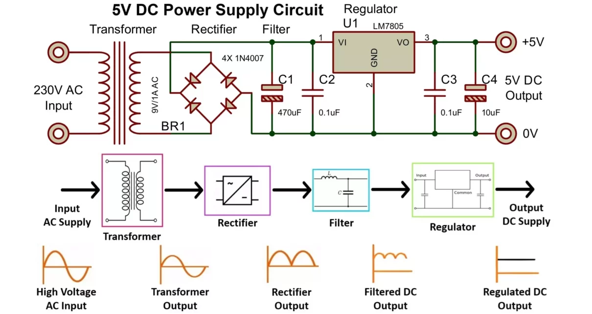
A DC voltage source is required to power electronic circuits. Here, we convert AC to DC using a step-down transformer, rectifier circuit, and voltage regulator. Let’s understand regulated power supply block diagram in detail.
1. Step-Down Transformation
A step-down transformer (TR1) reduces 220V AC to 6V AC (RMS value). The peak voltage of 6V RMS is given by: Vpeak = 6√2 = 8.5V, also peak voltage of 9V RMS is given by: Vpeak = 9√2 = 12.7V. The secondary voltage of the transformer should be slightly higher than the required regulated output, considering losses in the rectifier and regulator.
2. Rectification
A bridge rectifier, consisting of four 1N4007 diodes, converts the AC voltage into pulsating DC. Since this output still contains significant ripples, further smoothing is needed. The bridge rectifier allows full-wave rectification, ensuring higher efficiency and reduced ripple compared to a half-wave rectifier.
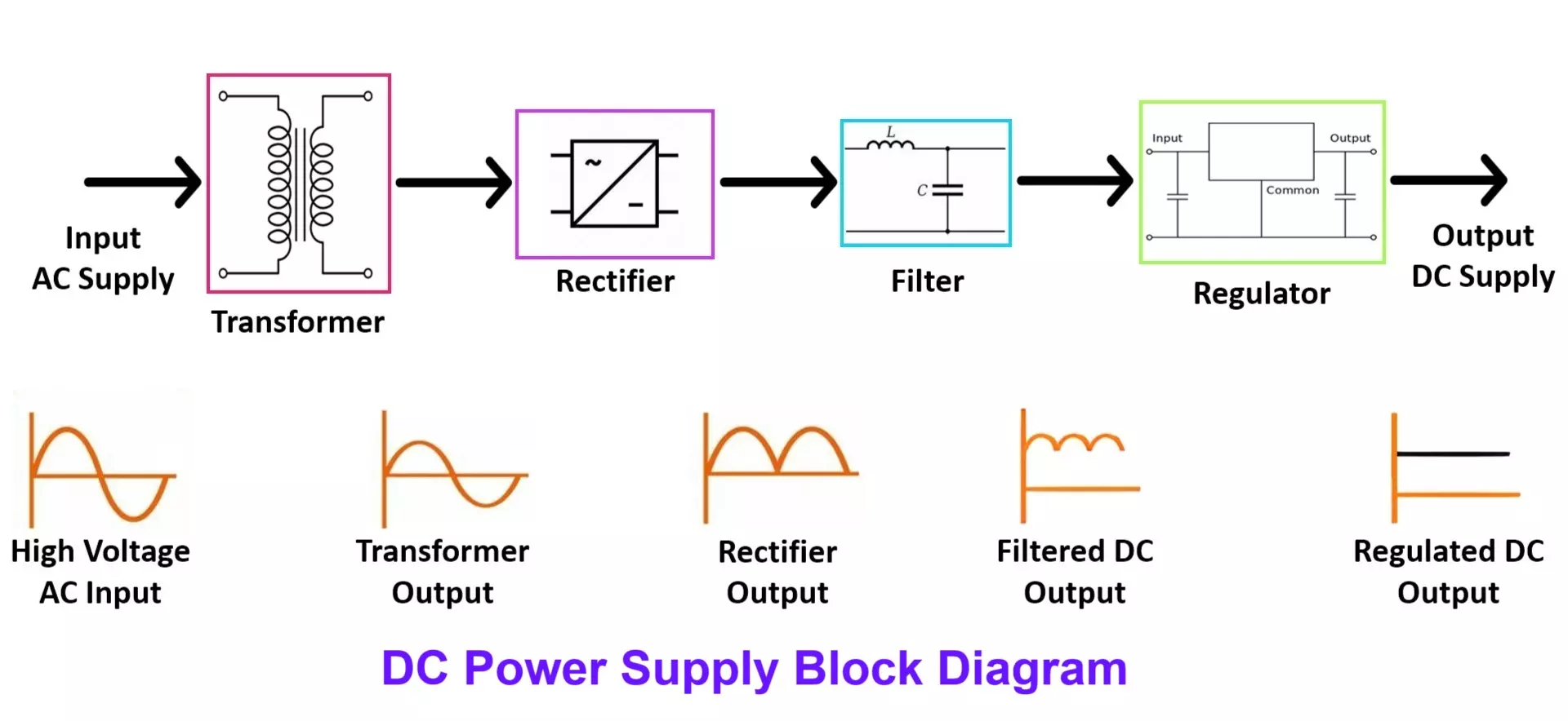
3. Filtering
A capacitor (C1) acts as a filter to smooth out the rectified DC voltage, reducing ripple content. This helps to provide a cleaner DC voltage before it enters the regulator. The capacitance value should be chosen appropriately, higher capacitance results in better ripple rejection but also a larger capacitor size.
4. Voltage Regulation
The filtered DC voltage is applied to the input of the 7805 IC, which regulates the output to a steady 5V. Additional capacitors (C2, C3 and C4) help maintain stability by counteracting voltage fluctuations caused by varying loads. These capacitors also help reduce noise in the power supply, ensuring proper operation of sensitive electronic circuits.
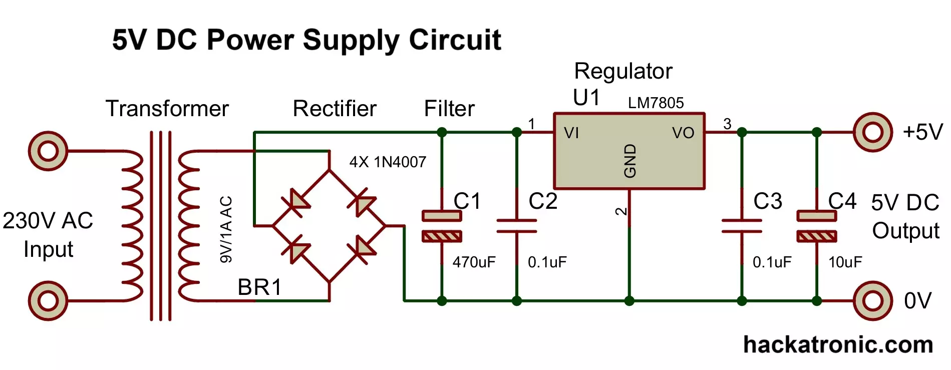
5V Power Supply Circuit Diagram
Assembly and Considerations
This circuit is simple and can be built on a PCB or breadboard. Key considerations include:
- Heat Dissipation: If the current stays below 250mA, the IC does not require a heatsink. However, higher currents generate more heat, making a heatsink necessary to prevent overheating. For even higher current demands, a switching regulator like the LM2576 offers a more efficient solution.
- Voltage Variations: The output voltage ranges from 4.85V to 5.15V, depending on input voltage and thermal conditions. Maintaining a stable input voltage improves accuracy and keeps the 5V output steady.
- Power Switch: Adding a switch to the AC side allows easy power control. Including a fuse enhances safety by protecting against overcurrent conditions.
- Alternative Components: For more precise and efficient voltage regulation, integrating a low-dropout (LDO) regulator such as the AMS1117-5.0 improves performance.
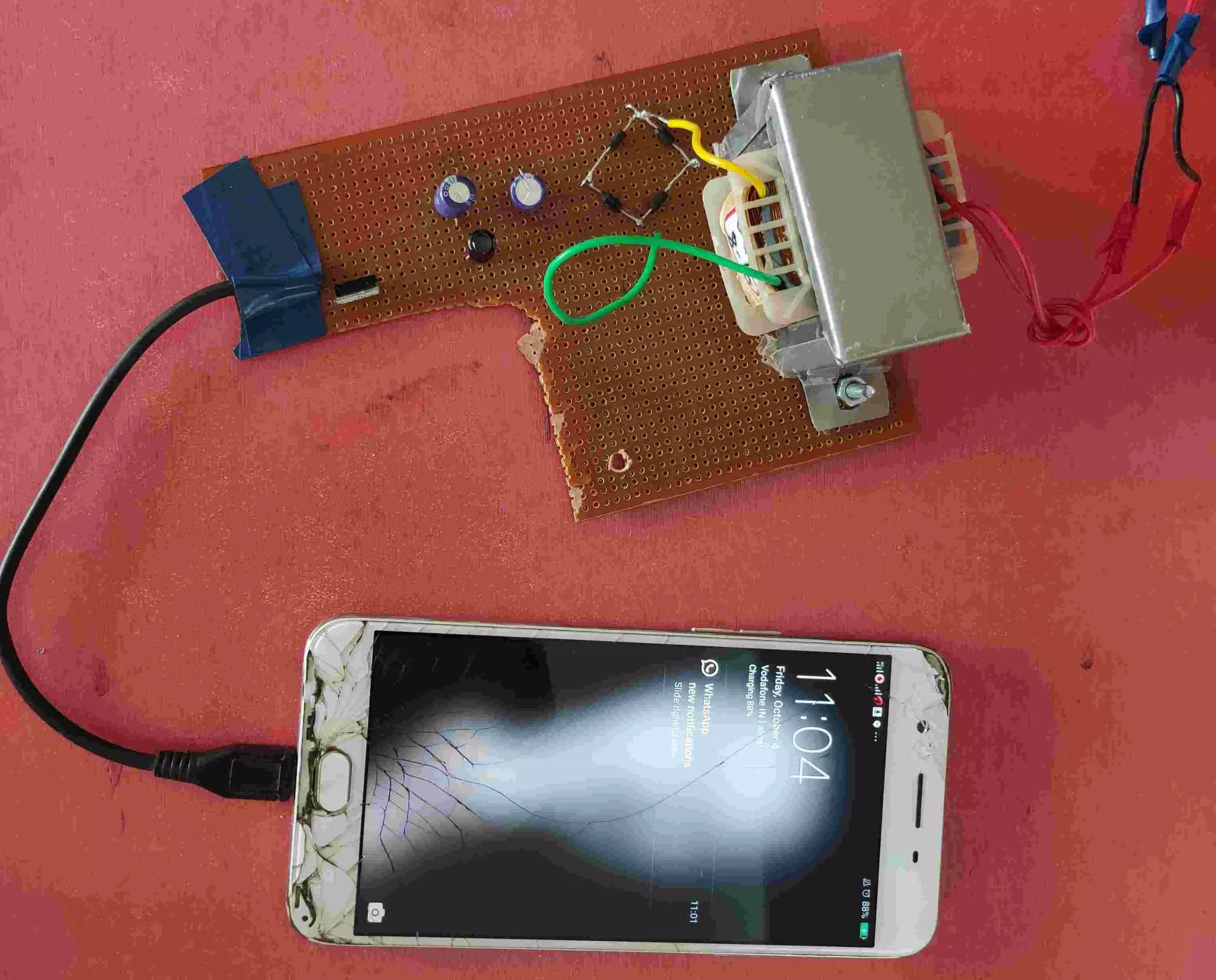
Output of the 5V Power Supply Circuit
This circuit provides a regulated 5V DC output suitable for powering electronic circuits, microcontrollers, and even charging mobile devices. The LM7805 ensures that the output voltage remains within a stable range, making it suitable for applications requiring precise voltage regulation.
By following this guide, you can easily build a reliable and efficient 5V power supply for your electronic projects. This power supply circuit is cost-effective and can be modified for higher current applications by using a parallel regulator setup or a higher-capacity transformer. Additionally, you can integrate this circuit with a USB port to power USB-based devices or small embedded systems.
12V 10A SMPS: Switched Mode Power Supply Circuit – IC DM0565
