A 4-bit synchronous counter using JK flip-flops is a sequential circuit that counts in a binary sequence (0000 to 1111), with all flip-flops receiving the clock pulse simultaneously, eliminating propagation delays found in asynchronous counters. Synchronous counters offer faster and more reliable counting operations, making them ideal for applications requiring precise timing. This article explores both up and down counter circuits, their working principles, advantages, disadvantages, timing diagrams, and applications, along with frequently asked questions.
Synchronous Counter Circuits:
Before Diving into design and applications, let’s explore some key terminologies used in synchronous counters.
1. Clock Pulse
A periodic signal that triggers the counter operation. The frequency of this signal determines the counting speed. Since all flip-flops receive the clock pulse simultaneously, the transitions occur in synchronization, minimizing timing errors and propagation delays.
2. 4 Bit Binary Counter
A 4-bit synchronous binary counter counts from 0000 to 1111 (0 to 15 in decimal) before resetting back to 0000. Each bit represents a binary-weighted value, and the counter progresses sequentially with each clock pulse.
3. Flip-Flops Used in Synchronous Counters
Synchronous counters typically use the following types of flip-flops:
- JK Flip-Flop: Can toggle, hold, set, or reset based on input conditions.
- D Flip-Flop: Directly transfers input D to the output Q at the clock edge.
- T Flip-Flop: Toggles its state on each clock pulse.
4. Logic Gates in Counter Design
Synchronous counters use logic gates such as:
- AND: Enables transitions based on conditions.
- OR: Combines signals.
- NOT: Inverts signals.
- XOR: Used in Gray code and parity. (Less common)
- NAND/NOR: Used for efficient counter design.
5. Specialized Counters
- Gray Code Counter: Counts using Gray code to minimize bit changes (Synchronous).
- Johnson Counter: A twisted ring counter cycling through unique states Asynchronous.
- Ring Counter: Circulates a single ‘1’ or ‘0’ through a shift register (Asynchronous).
- Decade Counter (BCD Counter): Counts from 0 to 9 (Binary-Coded Decimal format) (Synchronous).
6. Up Counter & Down Counter
- Up Counter: Counts in an increasing sequence (0000 → 0001 → 0010 → … → 1111).
- Down Counter: Counts in a decreasing sequence (1111 → 1110 → … → 0000).
- Up/Down Counter: Can be configured to count in either direction based on control input.
7. Clock Synchronization
All flip-flops in a synchronous counter receive the same clock signal simultaneously, ensuring that all transitions occur at the same time, avoiding glitches and propagation delays common in asynchronous counters.
8. Propagation Delay
Propagation delay is the time taken for the output of a flip-flop to change after a clock edge. In synchronous counters, propagation delay is minimized since all flip-flops operate in unison.
9. Modulus (MOD-N Counter)
A MOD-N counter cycles through N states before resetting. A 4-bit counter typically has MOD-16, counting from 0 to 15. By modifying feedback logic, it can be adjusted to any desired MOD value.
10. Ripple Effect
Ripple effect occurs in asynchronous counters due to sequential triggering. Synchronous counters eliminate this effect by applying the clock to all flip-flops simultaneously.
11. Preset & Clear (Reset)
- Preset (Set): Forces the counter to a specific state.
- Clear (Reset): Resets the counter to zero.
12. Enable Input
The enable input controls whether the counter increments or remains unchanged when a clock pulse is received.
13. Timing Diagram & State Diagram
- Timing Diagram: Shows how outputs change over time with clock pulses.
- State Diagram: Represents transitions between states in graphical form.
14. Parallel Load
Allows loading a specific value directly into the counter rather than counting from zero.
15. Synchronous Reset
A reset that occurs in sync with the clock signal, preventing timing issues.
16. Frequency Division
Counters can be used to divide clock frequency. A MOD-16 counter divides the input frequency by 16.
17. Cascading Counters
Counters can be cascaded to create higher bit-width counters (e.g., two 4-bit counters form an 8-bit counter).
18. Carry Output
The carry output is triggered when the counter reaches its maximum count, useful in cascading multiple counters.
19. Programmable Counter
A counter that can be configured to count a specific range by adjusting feedback connections.
20. Transition States
The sequence of binary states the counter moves through during operation.
21. Difference Between Synchronous and Asynchronous Counters
| Feature | Asynchronous Counter | Synchronous Counter |
|---|---|---|
| Clocking | Different clocks | Same clock |
| Propagation Delay | High | Low |
| Speed | Slow | Fast |
| Glitches | Possible | Minimized |
4-Bit Synchronous Counters by JK Flip-Flop
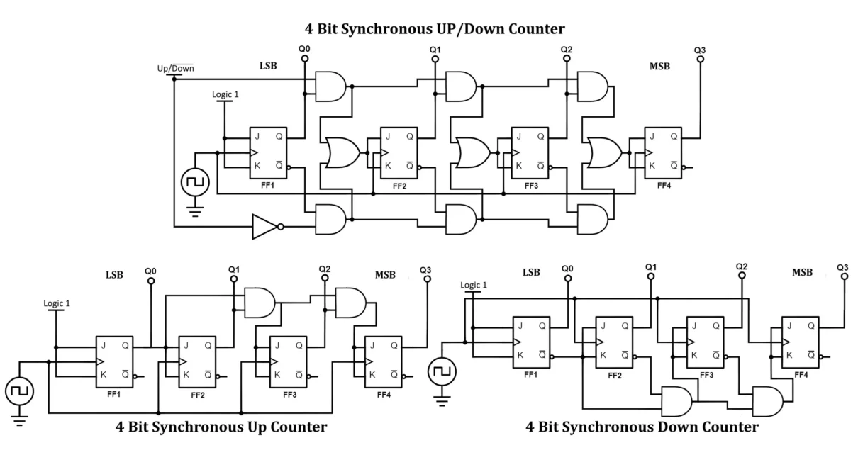
1. Construction of 4-bit Synchronous Counters
A. 4-bit Synchronous Up Counter Using JK Flip-Flops
- A 4-bit counter requires four JK flip-flops (FF0 to FF3), connected in a way that ensures synchronous operation.
- The clock input is applied to all flip-flops simultaneously.
- The output of each flip-flop represents a binary digit, with FF0 as the least significant bit (LSB) and FF3 as the most significant bit (MSB).
- Toggling of flip-flops occurs based on the previous state.
Circuit Diagram:
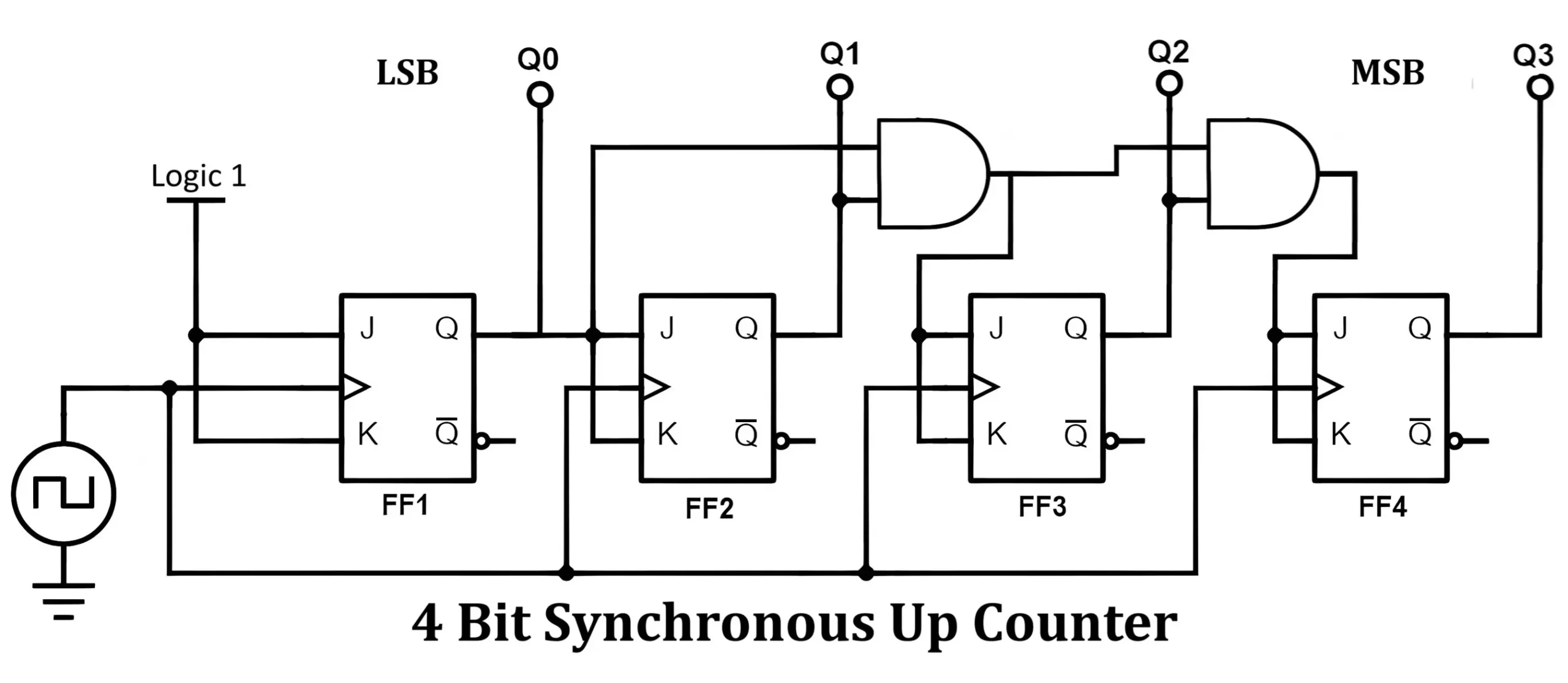
- Each flip-flop’s J and K inputs are set to HIGH (1) for toggling.
- The first flip-flop (FF0) toggles with every clock pulse.
- Each subsequent flip-flop toggles when all the previous flip-flop outputs are HIGH.
Truth Table:
| Clock Pulse | Q3 | Q2 | Q1 | Q0 |
|---|---|---|---|---|
| 0 | 0 | 0 | 0 | 0 |
| 1 | 0 | 0 | 0 | 1 |
| 2 | 0 | 0 | 1 | 0 |
| 3 | 0 | 0 | 1 | 1 |
| … | … | … | … | … |
| 15 | 1 | 1 | 1 | 1 |
| 16 (Clear) | 0 | 0 | 0 | 0 |
B. 4-bit Synchronous Down Counter Using JK Flip-Flops
- The design is similar to the up counter but modified to count in reverse order (1111 to 0000).
- Instead of toggling on all HIGH states, each flip-flop toggles when all lower significant bits are LOW.
Circuit Diagram:
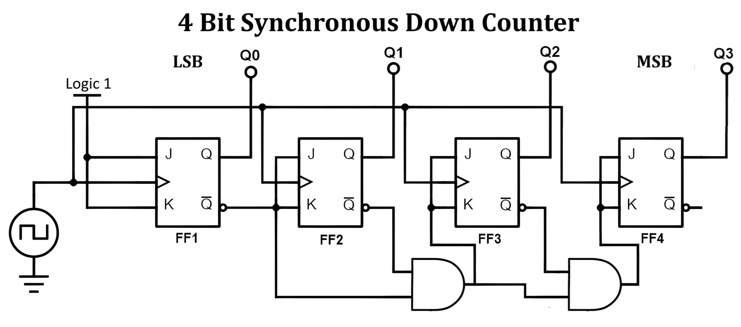
- The J and K inputs of first flip-flops is set to HIGH.
- FF0 toggles at every clock pulse.
- FF1 toggles when FF0 is LOW, and so on.
Truth Table:
| Clock Pulse | Q3 | Q2 | Q1 | Q0 |
| 0 | 1 | 1 | 1 | 1 |
| 1 | 1 | 1 | 1 | 0 |
| 2 | 1 | 1 | 0 | 1 |
| 3 | 1 | 1 | 0 | 0 |
| … | … | … | … | … |
| 15 | 0 | 0 | 0 | 0 |
| 16 (Reset) | 1 | 1 | 1 | 1 |
C. 4-Bit Synchronous Up/Down Counter Using JK Flip-Flop
A 4-bit synchronous up/down counter is capable of counting both in increasing (up) and decreasing (down) order. It utilizes a control input to determine the counting direction. Components of an Up / Down counter are listed below.
- Four JK Flip-Flops (FF0, FF1, FF2, FF3)
- AND, OR, and NOT logic gates
- A common clock signal
- A control input (UP/DOWN)
Circuit Design:
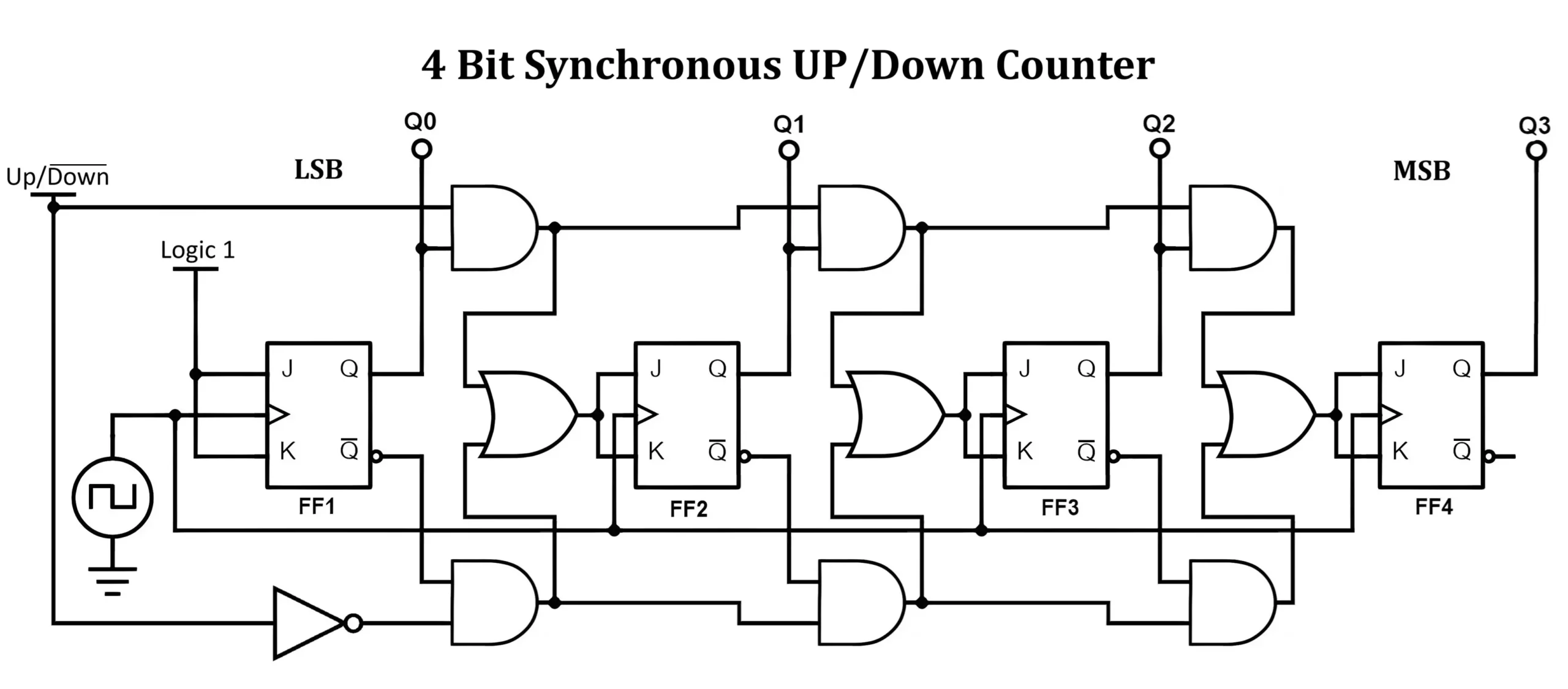
- The clock input is applied to all four JK flip-flops simultaneously.
- The control signal determines whether the counter operates in the up or down mode:
- UP Mode: The next state depends on the previous flip-flops’ outputs.
- DOWN Mode: The next state depends on the complemented outputs.
- Additional AND and OR gates control the toggling logic based on the UP/DOWN input.
Truth Table:
| Clock Pulse | UP/DOWN | Q3 | Q2 | Q1 | Q0 |
|---|---|---|---|---|---|
| 0 | 1 (UP) | 0 | 0 | 0 | 0 |
| 1 | 1 (UP) | 0 | 0 | 0 | 1 |
| 2 | 1 (UP) | 0 | 0 | 1 | 0 |
| 3 | 1 (UP) | 0 | 0 | 1 | 1 |
| 4 | 1 (UP) | 0 | 1 | 0 | 0 |
| … | … | … | … | … | … |
| 15 | 1 (UP) | 1 | 1 | 1 | 1 |
| 16 | 0 (DOWN) | 1 | 1 | 1 | 0 |
| 17 | 0 (DOWN) | 1 | 1 | 0 | 1 |
| 18 | 0 (DOWN) | 1 | 1 | 0 | 0 |
| 19 | 0 (DOWN) | 1 | 0 | 1 | 1 |
| … | … | … | … | … | … |
| 31 | 0 (DOWN) | 0 | 0 | 0 | 0 |
2. Working of a 4-bit Synchronous Counters
- Up Counter:
- FF0 toggles on each clock pulse.
- FF1 toggles when FF0 and previous states are HIGH.
- FF2 toggles when FF1 and FF0 are HIGH.
- FF3 toggles when all previous bits are HIGH.
- Down Counter:
- FF0 toggles on each clock pulse.
- FF1 toggles when FF0 is LOW.
- FF2 toggles when FF1 and FF0 are LOW.
- FF3 toggles when all previous bits are LOW.
- Up Down Counter:
- Up Mode Operation:
- When UP/DOWN = 1, the counter increments with each clock pulse.
- FF0 toggles on every clock pulse.
- FF1 toggles when FF0 is HIGH, FF2 toggles when FF1 and FF0 are HIGH, and so on.
- The counter continues until it reaches 1111 (decimal 15), then resets to 0000.
- Down Mode Operation:
- When UP/DOWN = 0, the counter decrements with each clock pulse.
- FF0 toggles on every clock pulse.
- FF1 toggles when FF0 is LOW, FF2 toggles when FF1 and FF0 are LOW, and so on.
- The counter continues until it reaches 0000, then resets to 1111.
- Up Mode Operation:
3. Timing Diagram of 4-bit Synchronous Counters
A timing diagram illustrates the transitions of each flip-flop output over time with respect to the clock pulse. The diagram shows the synchronous operation of all flip-flops, ensuring stable and glitch-free counting.
4-bit Synchronous UP Counter Timing Diagram
- The counter increments on each rising edge of the clock.
- Each bit toggles in a binary counting sequence from
0000to1111and then resets to 0000.
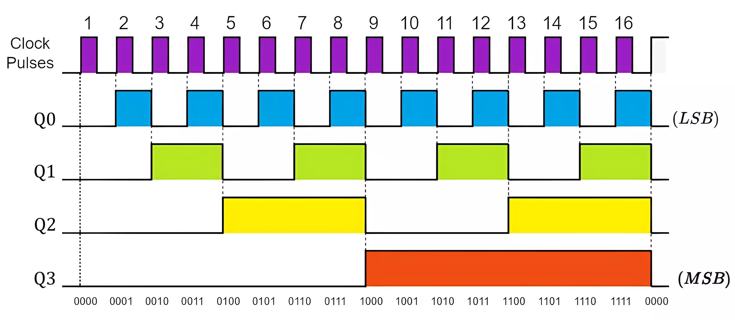
- Clock pulses trigger a synchronous update.
- Q0 toggles on every clock pulse.
- Q1 toggles after every 2 pulses, Q2 after 4 pulses, and Q3 after 8 pulses.
- The counter goes from
0000 → 1111, then rolls to0000
4-bit Synchronous DOWN Counter Timing Diagram
- The counter decrements on each rising edge of the clock.
- Each bit toggles in a reverse binary sequence from
1111to0000and then resets.
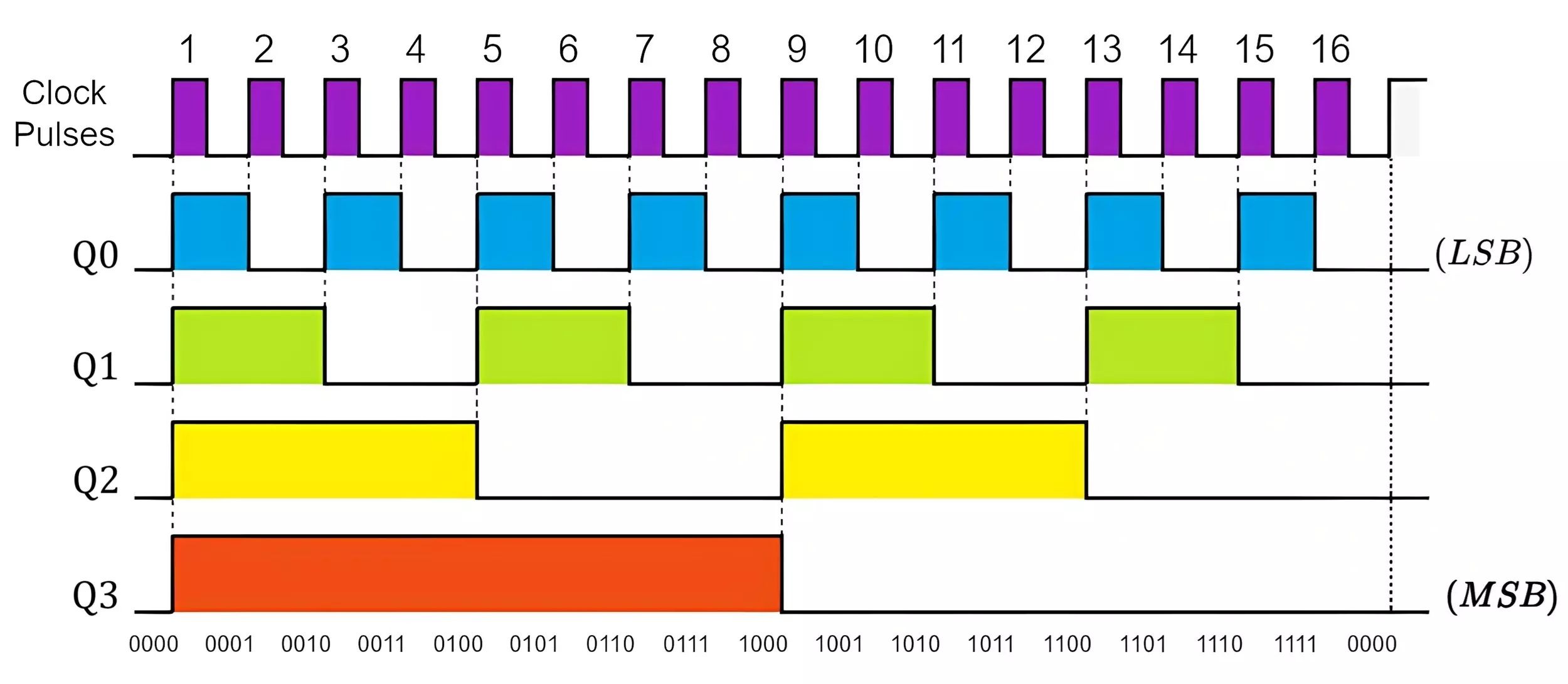
- Q0 changes on every clock pulse.
- Each bit toggles in reverse order compared to the UP counter.
- Starts at
1111(15) and counts down to0000(0). - Once
0000is reached, it rolls back to1111.
Advantages of Synchronous Counter Circuits
- Eliminates Propagation Delay – Since all flip-flops are triggered simultaneously, there is minimal propagation delay compared to asynchronous counters.
- Higher Speed – Synchronous counters can operate at higher clock speeds due to reduced delays.
- Reliable and Stable – The absence of cumulative delays makes them more reliable in precise timing applications.
- Ease of Design – Since all flip-flops receive the same clock signal, designing complex counters (e.g., up/down counter, modulo-N counter) is easier.
- Glitch-Free Output – Synchronous operation ensures smooth and predictable state transitions without glitches.
Disadvantages of Synchronous Counter Circuits
- Complex Circuitry – Synchronous counters require additional logic gates to control simultaneous transitions, increasing circuit complexity.
- Higher Power Consumption – The simultaneous triggering of all flip-flops may lead to higher power consumption compared to some asynchronous designs.
- Limited Fan-Out – Since all flip-flops receive the same clock pulse, the clock driver must handle multiple loads, which may require additional buffering.
- Design Constraints – For large-scale counters, complex combinational logic may slow down performance or require optimizations.
Applications of Synchronous Counter Circuits
- Frequency Division – Used in digital clocks, communication systems, and frequency synthesizers to divide a high-frequency signal into lower frequencies.
- Digital Clocks & Timers – Essential in electronic clocks, stopwatches, and timer circuits for precise counting and timekeeping.
- Event Counting – Used in event counters, traffic light controllers, and industrial automation for keeping track of occurrences.
- Memory Addressing – Synchronous counters are used in memory addressing to sequence through memory locations.
- State Machines – Used in control systems, digital signal processing, and embedded systems for implementing state-dependent operations.
- Electronic Voting Machines – Utilized to count votes accurately in digital polling systems.
- Data Synchronization – Helps in synchronizing multiple data streams in communication systems.
Conclusion
A 4-bit synchronous counter using JK flip-flops is an efficient and high-speed counting circuit used in various digital applications. Whether used as an up counter or down counter, it provides stable, glitch-free counting. Its applications range from digital clocks to microcontrollers and automation systems. By using appropriate flip-flops, logic gates, and control signals, synchronous counters can be designed for various applications, including frequency division, digital clocks, and control circuits. Some of the popular synchronous counter ICs are 74LS163 and 74HC4520.
Frequently Asked Questions (FAQ)
Q1: Why is a synchronous counter preferred over an asynchronous counter?
A: A synchronous counter eliminates propagation delay, ensuring faster and accurate counting operations.
Q2: How does a synchronous counter differ from an asynchronous counter?
A: In a synchronous counter, all flip-flops receive the clock pulse simultaneously, whereas in an asynchronous counter, the clock signal propagates sequentially.
Q3: How do you convert an up counter into a down counter?
A: By altering the toggling logic such that flip-flops toggle when lower bits are LOW instead of HIGH.
Q4: What is the maximum count of a 4-bit synchronous counter?
A: It can count from 0 (0000) to 15 (1111), making it a MOD-16 counter.
Q5: Can a 4-bit synchronous counter be used as a frequency divider?
A: Yes, each bit of the counter provides a divided frequency output.
Q6: What type of flip-flop is most commonly used in synchronous counters?
A: JK and D flip-flops are commonly used due to their ability to toggle and store data efficiently.
Q7: What is a MOD counter?
A: A MOD-N counter counts up to a specified number (N) before resetting to zero.
Q8: How does a synchronous counter minimize glitches?
A: All flip-flops receive the clock pulse simultaneously, reducing timing mismatches.
Q9: What is the function of a Johnson counter?
A: A Johnson counter cycles through a modified ring counter sequence, doubling the count states compared to a normal ring counter.
Q10: How can a counter be made programmable?
A: By implementing logic to load a custom value and adjusting feedback to set the counting range.
JK Flip Flop Truth Table, Circuit Diagram, Working & Applications
