Here is a simple proximity sensor circuit which shows proximity of an object by LED bar graph. Also, you will see two other simple proximity sensor designs.
Proximity sensors are devices that detect the presence of an object within a certain range without any physical contact. They are widely used in various applications such as industrial automation, mobile phones, and security systems. A common type of proximity sensor is the infrared (IR) proximity sensor.
BJT Based IR Proximity Sensor Circuit:

Circuit Components:
- IR LED: Emits infrared light.
- Photodiode/Phototransistor: Receives the reflected IR light from the object.
- Resistors (R1, R2): Used to limit current and set the operating points of components.
- Transistor (Q1, Q2): Acts as a switch to amplify the signal.
- Buzzer (SG1): Creates alarm when object is detected.
- Power Supply (Vcc & GND): Typically, 5V to 12V DC depending on the sensor requirements.
Working Principle:
- Emission: The IR LED emits infrared light continuously.
- Reflection: When an object comes within the range of the sensor, the IR light reflects off the object.
- Detection: The reflected IR light is detected by the photodiode/phototransistor.
- Signal Processing and Output:
- The photodiode/phototransistor converts the received IR light into a small current.
- This current causes a voltage drop across resistor R2 and a voltage signal is produced.
- If the signal exceeds 0.7V, the output of BJT Q2 goes high, If the signal is below the reference voltage, the output remains low, indicating no object is detected.
- The signal is then amplified by the transistor Q2 which turns on transistor Q1.
- The Transistor Q1 is used to drive LED3 and Buzzer.
Steps to Build the Circuit:
- Connect the IR LED: Connect the IR LED in series with a current-limiting resistor (R1) to GND.
- Position the Photodiode/Phototransistor: Place the photodiode or phototransistor in such a way that it can receive the reflected IR light.
- Add the Resistors: Add 3MΩ Resistor R2 in series with photodiode as per circuit to ensure proper signal conditioning.
- Transistor Stage: Connect the transistor (Q1, Q2) to amplify the signal received by the photodiode/phototransistor.
- Power Supply: Ensure the entire circuit is powered with the correct voltage supply.
Proximity Sensor by LM358 IC:

Circuit Components:
- IR LED: Emits infrared light.
- Photodiode/Phototransistor: Receives the reflected IR light from the object.
- Resistors (R1, R2, R3, R4, RP1): Used to limit current and set the operating points of components.
- Transistor (Q1): Acts as a switch and amplifies the signal.
- Op-Amp (U1): LM358 IC Compares the signal from the photodiode to a reference value.
- Power Supply (Vcc and GND): Typically, 5V to 12V DC depending on the sensor requirements.
Working of Proximity Sensor by LM358:
- Emission: The IR LED emits infrared light continuously.
- Reflection: When an object comes within the range of the sensor, the IR light reflects off the object.
- Detection: The reflected IR light is detected by the photodiode/phototransistor.
- Signal Processing and Output:
- The photodiode/phototransistor converts the received IR light into a small current.
- This current causes a voltage drop across resistor R1, 10K.
- This signal is fed to the comparator or operational amplifier IC LM358.
- The comparator in LM358 compares this signal to a reference voltage set by RP1.
- If the signal exceeds the reference voltage, the output of the comparator goes high, indicating the presence of an object.
- If the signal is below the reference voltage, the output remains low, indicating no object is detected.
Steps to Build the Circuit:
- Connect the IR LED: Connect the IR LED in series with a current-limiting resistor (R2).
- Place Photodiode/Phototransistor: Position the photodiode or phototransistor in such a way that it can receive the reflected IR light.
- Add the Resistors: Connect the appropriate resistors (R1, R3, R4, RP1) as per the circuit diagram to ensure proper signal conditioning.
- Transistor Stage: Connect the transistor (Q1) to amplify the signal received from LM358 IC and drive LED3.
- Comparator/Op-Amp: Add operational amplifier LM358 IC to process the signal and provide a digital output.
- Power Supply: Ensure the entire circuit is powered with the correct voltage supply.
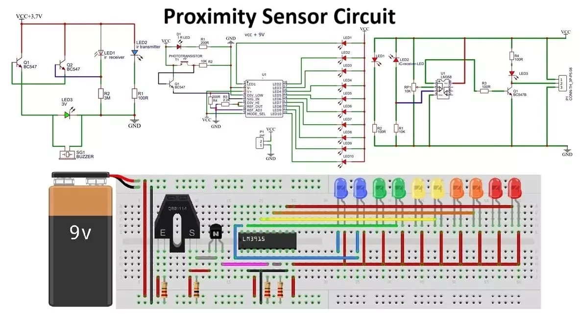
Proximity Sensor Circuit with LED Bar-Graph:
Below is a simple circuit diagram for an IR proximity sensor with LED bar graph:

Circuit Components:
- IR LED: Emits infrared light (QRB1114 is an alternate module).
- Photodiode/Phototransistor (T1): Receives the reflected IR light from the object.
- Resistors (R1, R2, R3, R4): Used to limit current and set the operating points for components.
- Transistor (Q1): Acts as a switch and amplifies the signal.
- LM3915 IC (U1): An 18-pin integrated circuit that detects analog signal voltage levels and drives a 10-LED bar or dot display accordingly.
- 10 LEDs: 5 pair of LEDs Red, Orange, Yellow Green and Blue.
- Power Supply (Vcc & GND): Typically, 5V or 12V DC depending on the sensor requirements.
IR Proximity Sensor Working Principle:
Emission: The IR LED present in QRB1114 module emits infrared light continuously.
Reflection: When an object comes within the range of the sensor, the IR light reflects off the object.
Detection: The reflected IR light is detected by the phototransistor present in QRB1114 module.
Signal Processing and Display:
- The phototransistor converts the received IR light into a small current.
- This current causes a voltage drop across resistor R2.
- The signal is then amplified by the transistor Q1.
- The amplified signal is fed to the LM3915 IC that detects analog signal voltage levels and drives LED.
- The LM3915 IC will compare the input signal with reference voltage level and drives 10 LED bar or dot display accordingly.

Steps to Build the Circuit:
- Connect the IR LED: Connect IR LED in series with a current-limiting resistor (R1) to GND.
- Position the Photodiode/Phototransistor: Place the photodiode or phototransistor in such a way that it can receive the reflected IR light. Add R2 in series with phototransistor.
- Transistor Stage: Connect the transistor (Q1) to amplify the signal received by the photodiode/phototransistor.
- LM3915 IC: Integrate the LM3915 IC with circuit to process the signal and provide a digital output to control LEDs.
- Power Supply: Ensure the entire circuit is powered with the correct voltage supply.
Testing the Circuit:
- Power On: Supply the circuit with the specified voltage.
- Object Detection: Place an object within the detection range of the sensor.
- Output Observation: Observe the output signal by LED, buzzer, or any other output device connected to the Circuit output. The output should change state when an object is detected.
Proximity Sensor Applications:
Proximity sensors are widely used in various applications due to their ability to detect objects without physical contact. Here are some common applications of proximity sensors:
1. Industrial Automation
- Assembly Lines: Proximity sensors detect the presence or absence of parts on conveyor belts to ensure proper assembly processes.
- Robotic Systems: Used to detect the position of robotic arms and ensure they operate within safe distances from objects and humans.
- Packaging Machines: Ensure correct placement and orientation of products during packaging.
2. Mobile Devices
- Touchless Screen Control: Detects when the user’s hand or face is near the screen, enabling features like automatic screen wake or lock.
- Call Management: Turns off the display when the phone is close to the ear during a call to prevent accidental touches and save battery.
3. Automotive Industry
- Parking Assistance: Helps in parking by detecting obstacles around the vehicle and providing alerts to the driver.
- Collision Avoidance Systems: Enhances safety by detecting nearby vehicles or objects and triggering braking or steering adjustments.
- Hands-Free Trunk Opening: Allows the trunk to open automatically when the user approaches with the key fob.
4. Security Systems
- Intrusion Detection: Monitors doors and windows to detect unauthorized entry.
- Perimeter Protection: Installed around the perimeters of buildings or properties to detect trespassers.
5. Consumer Electronics
- Smart Home Devices: Used in smart lights and appliances to detect presence and adjust settings accordingly.
- Gaming Consoles: Enable motion detection and enhance the gaming experience by tracking user movements.
6. Healthcare
- Patient Monitoring: Detects the presence of patients in beds or wheelchairs to prevent falls and ensure safety.
- Medical Devices: Used in devices like infusion pumps to detect the correct placement and operation.
7. Manufacturing and Processing
- Material Handling: Detects the presence of materials in hoppers, bins, or conveyors to control feeding mechanisms.
- Quality Control: Ensures products are correctly positioned and oriented during manufacturing processes.
8. Transportation and Logistics
- Automated Guided Vehicles (AGVs): Used for navigation and obstacle detection in warehouses and factories.
- Traffic Management: Installed at intersections to detect the presence of vehicles and control traffic lights.
9. Aerospace and Defense
- Aircraft Proximity Warning Systems: Warns pilots of nearby obstacles or other aircraft.
- Missile Guidance Systems: Ensures the missile maintains the correct trajectory by detecting proximity to targets.
10. Agriculture
- Harvesting Equipment: Detects the presence of crops and helps automate the harvesting process.
- Livestock Management: Monitors the presence and movement of animals in farms.
11. Retail
- Customer Counting: Counts the number of customers entering and exiting stores for analytics.
- Product Placement: Ensures products are correctly placed on shelves and triggers restocking alerts when items are low.
12. Construction
- Heavy Machinery: Enhances safety by detecting nearby workers or obstacles.
- Material Detection: Identifies the presence of construction materials to automate handling processes.
13. Utilities
- Water and Waste Management: Detects the level of liquids in tanks and containers to control pumps and valves.
- Energy Management: Monitors the presence of personnel in rooms to control lighting and HVAC systems for energy savings.
Proximity sensors play a critical role in improving efficiency, safety, and convenience across various industries and applications.
The above simple IR proximity sensor circuits can be used as a basic model for understanding how proximity sensors work and can be further enhanced for specific applications.
