Battery chargers with automatic cut-off functionality are vital for protecting batteries from overcharging, enhancing their lifespan, and ensuring efficient operation. This guide explains how to build a simple 12V auto cut-off battery charger circuit using commonly available components, including a TL431 voltage reference IC, a MOSFET IRFZ44N, LEDs for status indication, and other basic components. See this battery voltage level indicator circuit for further improving your design.
Components Required for Charger Circuit:
- TL431 (Adjustable Precision Shunt Regulator) – 1 unit
- MOSFET IRFZ44N – 1 unit
- 10kΩ Potentiometer – 1 unit
- LEDs (Red & Green) – 2 units
- Resistors (1kΩ) – 3 units
- Diode (6A10 or 1N4007 or similar) – 1 unit
- Battery (12V Lead-Acid)
- Power Source (e.g., 15V DC supply)
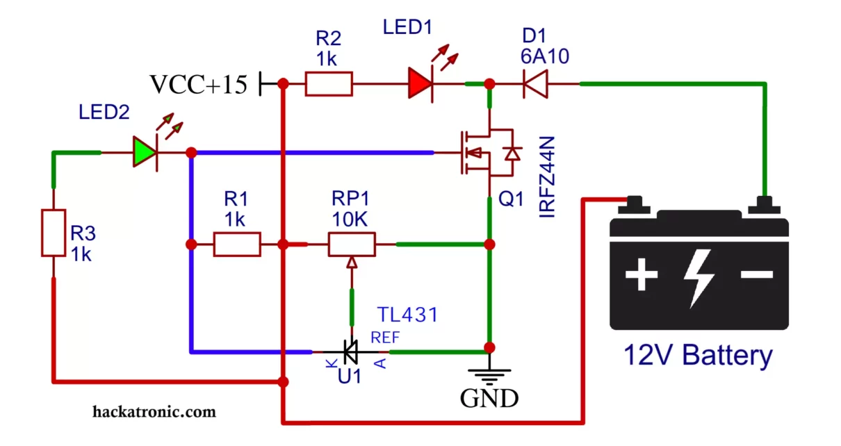
12V Battery Charger Circuit Diagram and it’s Working:
The circuit comprises three main sections: voltage reference, switching control, and status indication. Here’s an overview of the components and their roles in circuit operation:
Voltage Reference (TL431):
The TL431 is configured to act as a precision voltage reference. It is connected to the battery and senses the voltage through a voltage divider network.
The 10kΩ potentiometer is used to adjust the reference voltage for cut-off. This is set to the fully charged voltage of the 12V battery (e.g., 14.4V).
Switching Control (IRFZ44N):
The IRFZ44N MOSFET is used as the main switching device. When the battery voltage is below the cut-off threshold, the MOSFET remains on, allowing the charging current to flow to the battery.
Once the battery reaches the cut-off voltage, the TL431 triggers the MOSFET to turn off, cutting the charging current.
Status Indication (LEDs):
Two LEDs (red and green) indicate the charging status.
The red LED turns on during charging, while the green LED lights up when the battery is fully charged, signaling cut-off.
Protection (Diode):
A diode is connected in series with the positive line to prevent reverse current flow from the battery to the power source when the charger is off.

Wiring Details of 12V Battery Charger Circuit:
TL431 Configuration:
- Connect the reference pin (Ref) of the TL431 to the voltage divider (potentiometer and resistor).
- The cathode (K) connects to the gate of the IRFZ44N MOSFET. (You may use 1kΩ resistor at gate).
- The anode (A) is grounded.
Voltage Divider:
Use a 10kΩ potentiometer and a 1kΩ resistor to form the voltage divider. Connect the potentiometer wiper to the TL431 reference pin.
MOSFET Connection:
- The drain of the IRFZ44N connects to the negative terminal of the battery through charging path.
- The source is connected to the ground.
LED Indicators:
- The green LED is connected between the gate of the MOSFET and positive supply, with a 1kΩ resistor in series.
- The red LED is connected between drain of MOSFET and positive supply, with a 1kΩ resistor in series.
Power Supply and Diode:
- Connect a 6A10 or 1N4007 or similar diode in series with the positive terminal of the power supply to prevent reverse polarity.
Calibration and Testing:
Adjusting Cut-Off Voltage:
Turn the potentiometer to set the cut-off voltage. Connect a voltmeter across the output terminals and fine-tune the potentiometer until the charger cuts off at 14.4V.
Testing the LEDs:
Ensure the red LED lights up during charging. Once the battery reaches the set voltage, the green LED should light up, indicating the charger is off.
Load Testing:
Test the circuit with a partially discharged 12V battery and monitor its behavior as the voltage approaches the cut-off threshold.
Watch this video for better understanding.
Advantages of Auto Cut Off Battery Charger:
- Simple and Cost-Effective: Uses minimal components for efficient operation.
- Battery Protection: Prevents overcharging, enhancing battery life.
- Visual Indication: LEDs provide clear feedback on the charging state.
Applications of Automatic Battery Charger:
- Charging 12V lead-acid batteries for automotive, solar, or backup power systems.
- Portable charging setups where overcharging protection is crucial.
You can make a 3.7V or 9V battery charger my modifying above circuit.
By following this guide, you can construct a reliable and efficient 12V auto cut-off battery charging protection circuit. This design is suitable for hobbyists and professionals alike, ensuring your battery charging process is safe and optimized.
