Let’s explore the various types of inductors, along with their unique properties and applications. An inductor is one of the fundamental passive components used in electrical and electronic circuits, along with resistors and capacitors. Inductors store energy in the form of a magnetic field when an electric current flows through them.
The property of an inductor that quantifies its behavior is called inductance, denoted by L and measured in Henries (H), named after the American scientist Joseph Henry, who discovered electromagnetic induction around the same time as Michael Faraday. They resist sudden changes in current, smooth voltage ripples, filter unwanted frequencies, and play key roles in energy conversion, signal conditioning, and electromagnetic interference (EMI) suppression.
Inductors oppose any change in current, a characteristic known as self-inductance. When current varies, an electromotive force (EMF) is induced, opposing the change in current according to Lenz’s Law. This makes inductors crucial in circuits involving energy storage, signal filtering, tuning, and power conditioning.
The construction of an inductor involves a coil of conductive wire, often copper, wound around a core. The core material significantly influences the inductance value, efficiency, and frequency response.
Among various circuit board components, an inductor is a coil of conductive wire, often copper, wound around a core. The core material significantly influences the inductance value, efficiency, and frequency response, making material selection critical for achieving the desired electrical performance.
For high-quality PCB manufacturing and assembly services, visit NextPCB
NextPCB offers a comprehensive one-stop solution for PCB manufacturing. Every component is verified for authenticity through our stringent Incoming Quality Control (IQC) process and sourced directly from suppliers, ensuring both reliability and reduced BOM costs.
Symbol of Inductor
The circuit symbol of an inductor is a coil of wire, representing the turns wound on a magnetic core or air core.
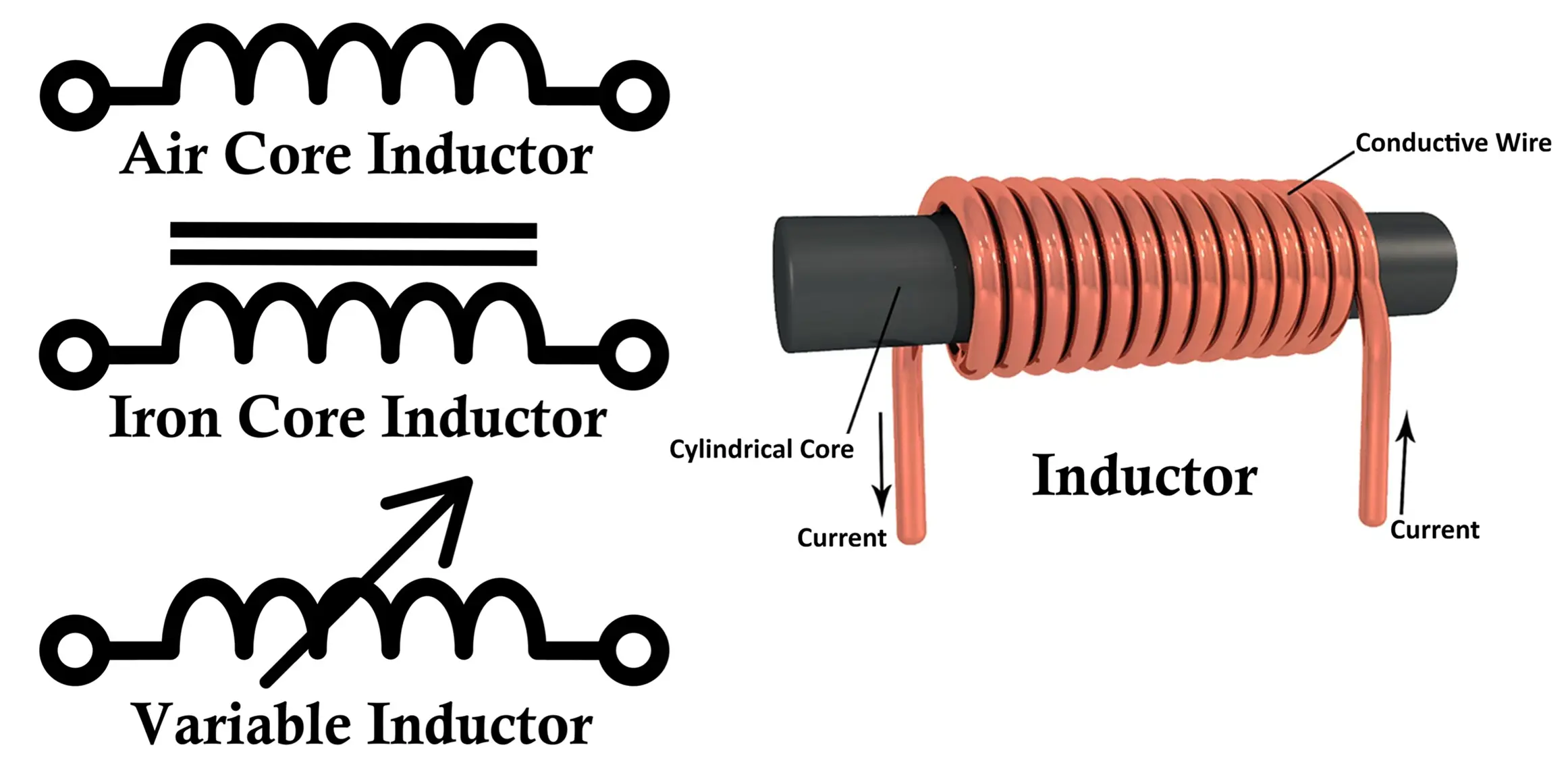
- Air-core inductor:
Represented by a simple coil shape (no magnetic core). - Iron-core inductor:
Represented by a coil with two parallel lines near it, indicating a magnetic core. - Variable inductor:
The diagonal arrow across the coil indicates that the inductance is adjustable.
Construction of an Inductor
An inductor is typically made by winding a conducting wire (usually copper) into a coil around a core material. The number of turns, the diameter of the wire, the spacing between the turns, and the core material determine the inductance value.
Main Components of an Inductor
- Conductive Wire:
Usually copper or aluminum, often insulated with an enamel coating to prevent shorting between turns. - Core Material:
The core is the central part on which the wire is wound. It affects the magnetic field strength and inductance.- Air core: used in high-frequency circuits.
- Iron core: used in power applications.
- Ferrite core: used in RF (radio frequency) applications for compact size and efficiency.
- Coil Winding:
The wire is wound in circular, toroidal, or solenoidal shapes. The inductance increases with the number of turns and the magnetic permeability of the core.

Inductance Formula
The inductance (L) of a solenoid (air-core coil) is given by:
L = (µ0µrN2A)/l
Where:
- L = Inductance in Henry (H)
- µ0 = Permeability of free space (4π × 10⁻⁷ H/m)
- µr = Relative permeability of the core material
- N = Number of turns in the coil
- A = Cross-sectional area of the core (m²)
- l = Length of the coil (m)
Working Principle of an Inductor
The working of an inductor is based on Faraday’s Law of Electromagnetic Induction, which states that a changing current through a coil induces an electromotive force (EMF) opposing that change.
When Current Flows:
When a voltage is applied to an inductor, current starts to flow, creating a magnetic field around the coil. This magnetic field stores magnetic energy proportional to the current.
When Current Changes:
If the current changes (increases or decreases), the magnetic field also changes. This variation in magnetic flux induces a back EMF (opposing voltage) in the coil according to Lenz’s Law, which opposes the change in current.
Energy Stored in an Inductor
The energy stored in an inductor is given by:
E = (1/2)LI2
Where:
- E = Energy stored in joules (J)
- L = Inductance (H)
- I = Current (A)
Thus, an inductor resists sudden changes in current and temporarily stores electrical energy in its magnetic field.
Properties of an Inductor
- Inductance (L):
The ability to store magnetic energy; depends on the coil geometry and core material. - Reactance (XL):
The opposition offered by the inductor to alternating current (AC) is called inductive reactance, given by:XL = 2πfL
where (f) is the frequency of the AC signal.
- Frequency Dependence:
Inductors allow DC to pass easily but oppose AC more strongly as frequency increases. - Q-Factor (Quality Factor):
Indicates the efficiency of an inductor; a higher Q means lower energy losses. - Self-Inductance:
The ability of a coil to induce an EMF in itself when the current changes. - Mutual Inductance:
The ability of one coil to induce EMF in another coil placed nearby (used in transformers).
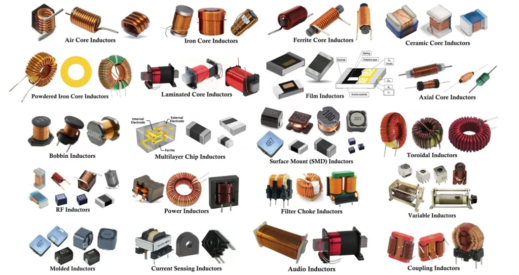
Different Types of Inductors
An inductor’s behavior and performance depend mainly on three factors: core material, construction type and functional purpose.
- The core material, which affects inductance and losses.
- The construction type, which influences its size, mounting, and efficiency.
- The functional purpose, which defines how it interacts within a circuit.
Let’s explore all types of inductors in detail under these three main categories:
- Core Material
- Air Core Inductors
- Iron Core Inductors
- Ferrite Core Inductors
- Ceramic Core inductors
- Laminated Core Inductor
- Powdered Iron Core Inductors
- Construction Type
- Toroidal Inductors
- Bobbin Inductors
- Multi-layer Inductors
- Film Inductors
- Axial Core Inductor
- Surface Mount (SMD) Inductor
- Functional Application
- RF Inductors
- AF Inductor
- Power Inductors
- Filter Inductor
- Variable Inductor
- Sensing Inductors
- Pulse Inductors
- Coupling Inductors
Each type of inductor has distinct magnetic properties, frequency ranges, and mechanical designs suited for specific electronic systems.
1. Types of Inductors Based on Core Material
The core material determines how efficiently an inductor can store magnetic energy and how it behaves at different frequencies. The most common materials are air, iron, ferrite, powdered iron, and laminated steel. Each offers unique trade-offs between inductance, saturation, losses, and cost.
1.1 Air Core Inductor
Construction & Working:
An air core inductor consists of a copper wire wound on a non-magnetic former made of plastic, ceramic, or simply a hollow tube (air). Since there is no magnetic material, the magnetic flux is generated entirely in the air.
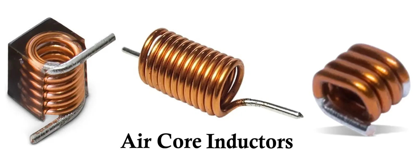
Properties:
- Magnetic permeability equals that of free space (μ₀).
- Zero core loss (no eddy or hysteresis losses).
- Extremely stable at high frequencies.
Advantages:
- Excellent linearity between current and inductance.
- No saturation or magnetic distortion.
- Ideal for precise, high-frequency tuning circuits.
Disadvantages:
- Very low inductance for a given number of turns.
- Bulky for low-frequency applications.
Applications:
- RF amplifiers, antennas, and oscillators.
- Tuned LC tank circuits.
- High-frequency communication systems.
1.2 Iron Core Inductor
Construction & Working:
Iron core inductors use a solid or laminated iron core inserted within the coil to increase magnetic flux density and inductance. Iron offers high permeability, enhancing the coil’s ability to store energy.
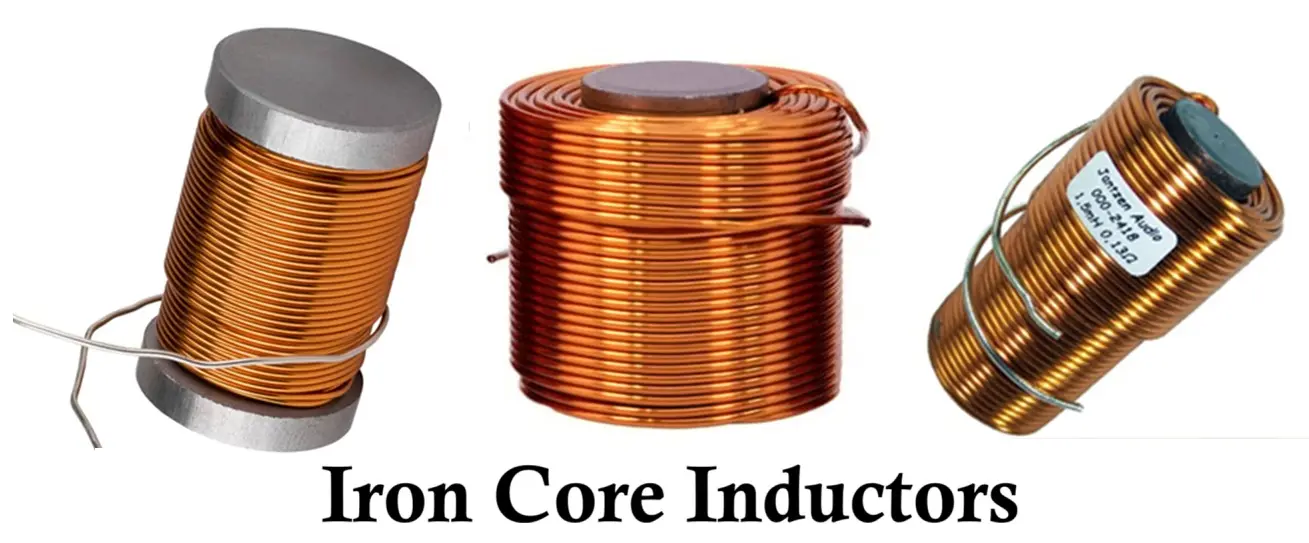
Properties:
- High inductance even with fewer turns.
- Suitable for low to medium frequencies (50 Hz – 10 kHz).
- May suffer from eddy current losses if unlaminated.
Advantages:
- Compact and powerful.
- Can handle large currents without overheating.
- Cost-effective for power and audio applications.
Disadvantages:
- Core losses increase rapidly at high frequencies.
- Saturation can occur at high magnetic fields.
Applications:
- Transformers, electromagnets, and chokes.
- Audio crossover networks.
- Low-frequency filters.
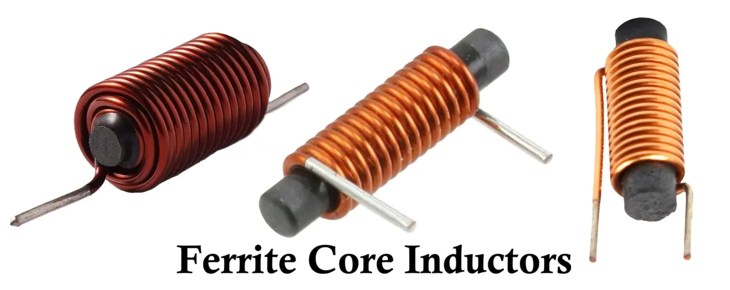
1.3 Ferrite Core Inductor
Construction & Working:
A ferrite core inductor uses a magnetic ceramic material (ferrite) composed of iron oxide mixed with metals such as nickel, zinc, or manganese. Its high resistivity minimizes eddy current losses, making it ideal for high-frequency circuits.
Properties:
- Very high magnetic permeability.
- Low electrical conductivity (reducing eddy currents).
- Suitable for frequencies from kHz to MHz ranges.
Advantages:
- High inductance in compact form.
- Excellent EMI suppression.
- High efficiency at high frequencies.
Disadvantages:
- Brittle structure prone to cracking.
- Can saturate under very high DC current.
Applications:
- RF transformers, EMI filters, and switching regulators.
- SMPS and DC-DC converters.
- Ferrite beads and RF chokes.
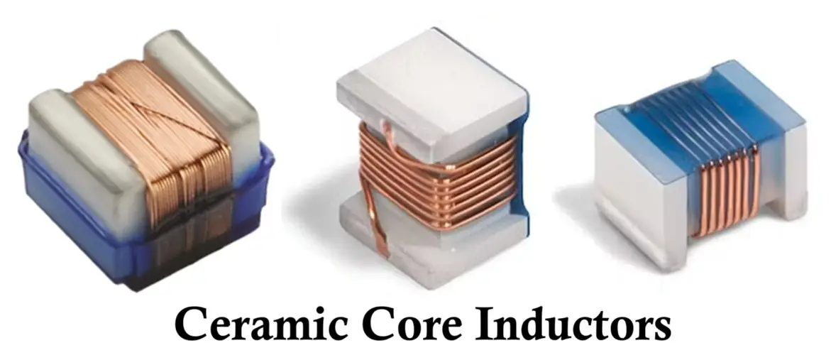
1.4 Ceramic Core Inductor
Construction & Working:
A ceramic core inductor consists of a copper wire wound around a solid ceramic rod or former. The ceramic material acts as a non-conductive, non-magnetic core that provides mechanical stability and a slight increase in inductance compared to air cores. The ceramic core helps maintain the coil’s shape and spacing, ensuring consistent inductance even under varying temperature and humidity conditions.
Properties:
- Magnetic permeability is approximately equal to that of air (μ ≈ μ₀).
- No core losses (eddy current and hysteresis losses are negligible).
- Excellent thermal and mechanical stability.
- High Q-factor (quality factor) at radio and microwave frequencies.
Advantages:
- Better mechanical strength and stability than air core inductors.
- Minimal core losses, making them suitable for high-frequency applications.
- Stable inductance value with temperature and environmental changes.
- Compact design compared to equivalent air core inductors.
Disadvantages:
- Inductance slightly lower than that of magnetic core inductors (e.g., ferrite).
- Still relatively bulky for low-frequency use.
- More expensive than air core designs in some cases.
Applications:
- RF and microwave circuits.
- Precision filters and oscillators.
- Tuned circuits in communication and measuring equipment.
- High-frequency impedance matching networks.
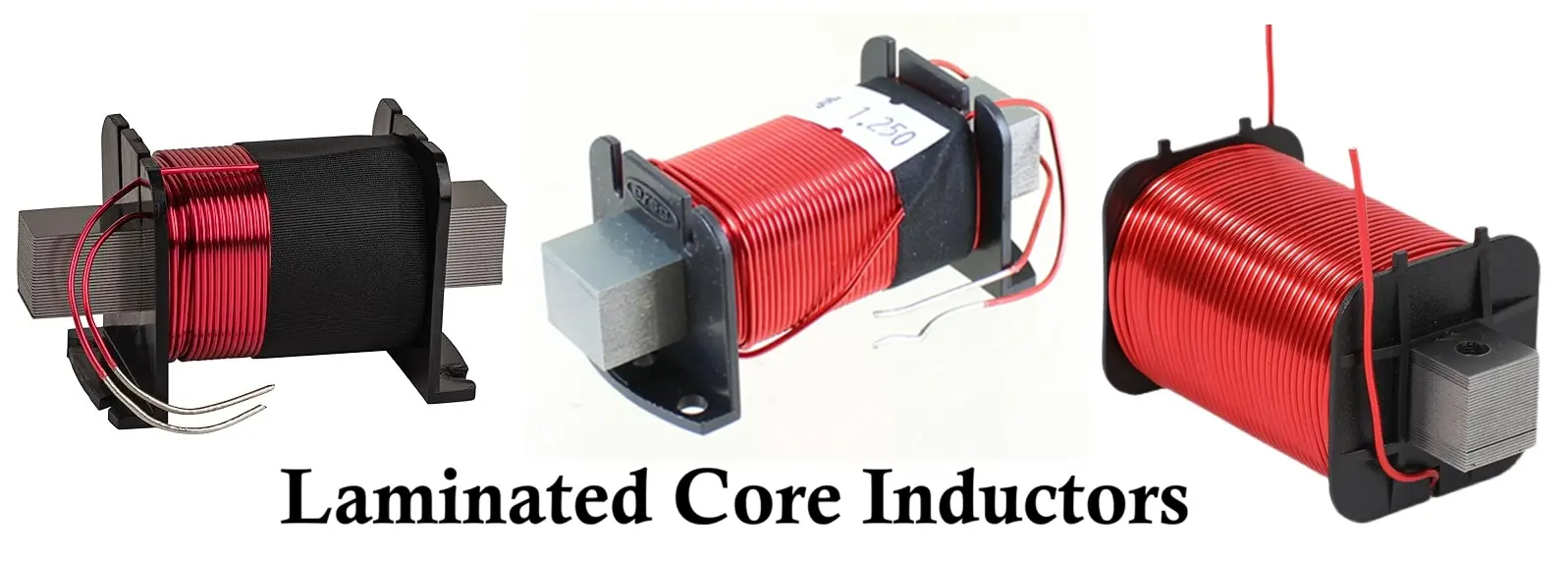
1.5 Laminated Core Inductor
Construction & Working:
This type uses stacked thin laminations of steel or iron, insulated from each other, to reduce eddy current paths. Laminations guide magnetic flux efficiently while minimizing energy losses.
Properties:
- High magnetic permeability.
- Low eddy current and hysteresis losses.
- Typically used in power frequency applications (50–60 Hz).
Advantages:
- Excellent magnetic efficiency.
- High power-handling capability.
- Mechanically strong and durable.
Disadvantages:
- Bulky and heavy.
- Inefficient at high frequencies due to eddy currents.
Applications:
- Power transformers and AC chokes.
- Industrial power conditioning.
- Audio transformers.
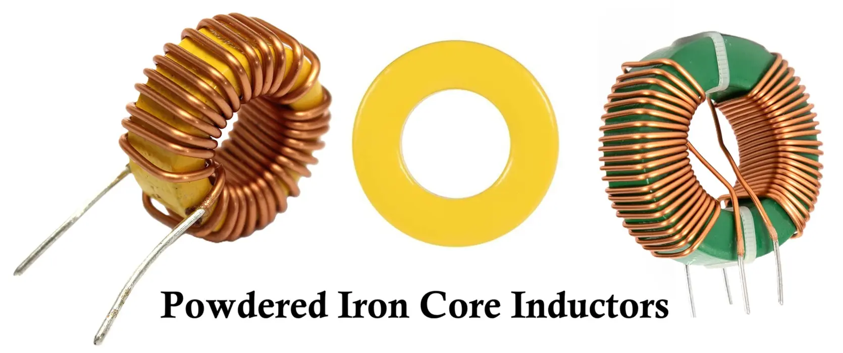
1.6 Powdered Iron Core Inductor
Construction & Working:
A powdered iron core is made by compressing fine iron particles mixed with a binder. Tiny air gaps between particles act as distributed gaps, preventing magnetic saturation and ensuring linear inductance across wide current ranges.
Properties:
- Moderate permeability.
- Low hysteresis and core loss.
- Excellent thermal stability.
Advantages:
- Can handle large DC bias currents.
- Maintains stable inductance under load.
- Compact and reliable for power circuits.
Disadvantages:
- Limited performance at very high frequencies (>1 MHz).
- Lower permeability than ferrite.
Applications:
- DC-DC converters and SMPS.
- Power filters and output chokes.
- Energy storage in buck and boost converters.
2. Types of Inductors Based on Construction
The physical construction and manufacturing technique determine the inductor’s size, mounting method, EMI characteristics, and frequency performance. These types are often selected based on packaging requirements and circuit layout constraints.
2.1 Toroidal Inductor
Construction & Working:
A toroidal inductor is wound on a circular magnetic ring (toroid). The closed magnetic path minimizes flux leakage, improving efficiency.
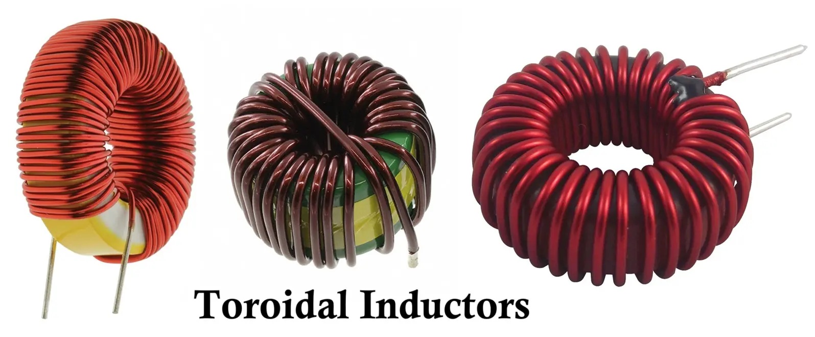
Properties:
- High magnetic coupling efficiency.
- Minimal electromagnetic interference (EMI).
- High inductance density.
Advantages:
- Compact and efficient.
- Low noise and high Q-factor.
- Ideal for energy storage applications.
Disadvantages:
- Complex winding process.
- Slightly higher cost.
Applications:
- SMPS, power conditioning, and EMI filters.
- Audio crossovers and RF circuits.
- Current sensors and transformers.
2.2 Bobbin Inductors
Construction & Working:
A bobbin inductor is wound on a cylindrical coil form (bobbin) made of plastic or other insulating material. The winding is often enclosed with a ferrite or laminated iron core to enhance inductance. The bobbin provides mechanical support and maintains uniform spacing between turns, ensuring consistent performance.
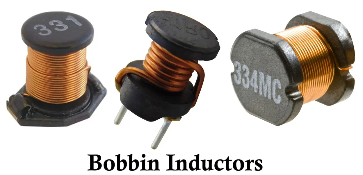
Properties:
- Easy to manufacture and handle.
- Provides good insulation and mechanical strength.
- Moderate magnetic coupling efficiency.
Advantages:
- Simple and cost-effective construction.
- Suitable for automated winding.
- Easy to mount on PCBs (especially with through-hole or SMD types).
Disadvantages:
- Higher flux leakage compared to toroidal inductors.
- Larger size for the same inductance value.
- Moderate EMI performance.
Applications:
- Power supplies and converters.
- Signal filtering and decoupling circuits.
- General-purpose energy storage and chokes.
2.3 Axial Core Inductor
Construction & Working:
This is a through-hole type inductor resembling a resistor, with wire leads on both ends. The wire is wound axially on a ferrite or iron core and sealed with epoxy.
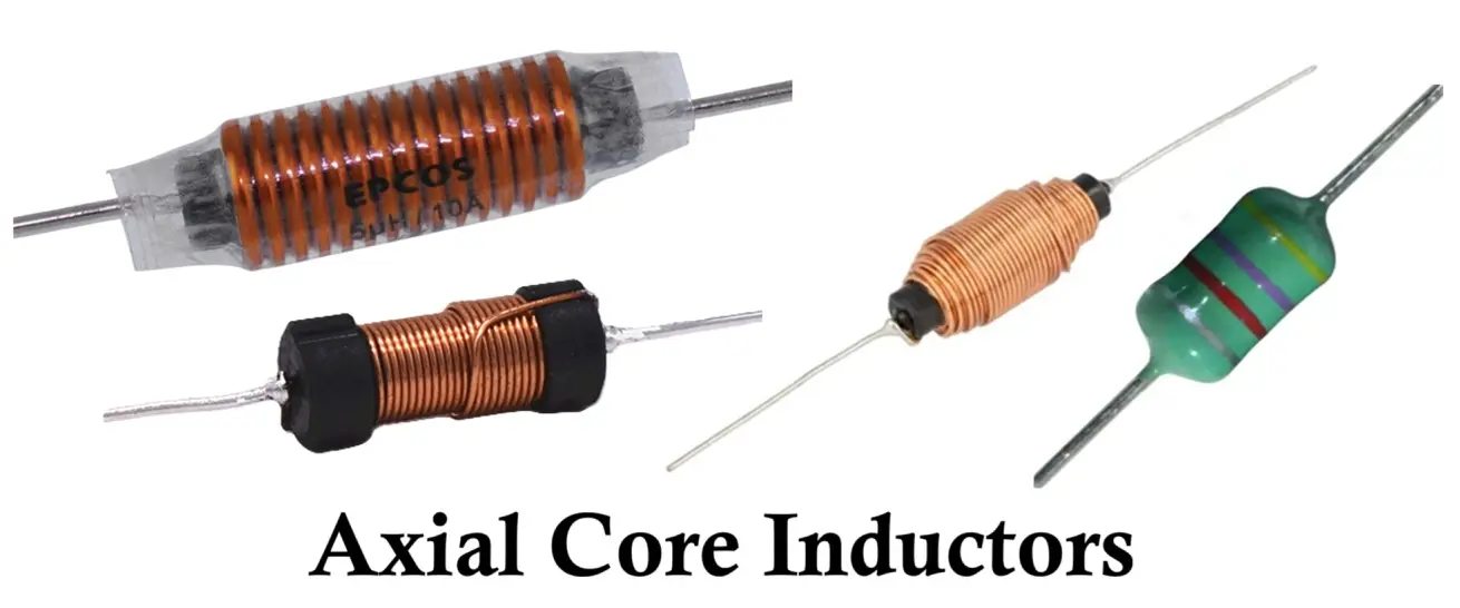
Properties:
- Compact cylindrical design.
- Standard color bands for identification.
- Available in various inductance values.
Advantages:
- Easy to mount on PCBs.
- Cost-effective and reliable.
- Standardized and widely available.
Disadvantages:
- Limited high-frequency performance.
- Restricted current-handling capacity.
Applications:
- Audio and low-frequency filtering.
- Decoupling circuits.
- Signal conditioning.
2.4 Multilayer Chip Inductor (MLCI)
Construction & Working:
Composed of multiple stacked layers of ceramic and conductive materials. Each layer contains a printed spiral pattern, forming a compact monolithic structure after sintering.
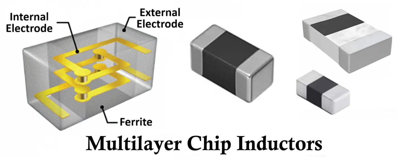
Properties:
- Extremely small and stable.
- High self-resonant frequency.
- Ideal for GHz-range applications.
Advantages:
- Perfect for miniaturized electronic circuits.
- Excellent temperature stability.
- Low losses and high precision.
Disadvantages:
- Fragile structure.
- Limited current capacity.
Applications:
- RF front-end circuits, Bluetooth, GPS, and Wi-Fi modules.
- Smartphones and wireless communication devices.
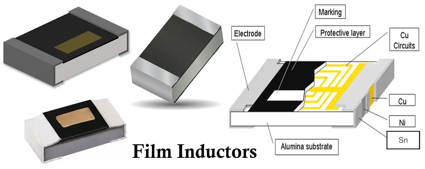
2.5 Film Inductor
Construction & Working:
In this type, a thin metallic film is deposited in a spiral pattern on a non-conductive substrate like glass or ceramic using photolithography.
Properties:
- Micro-scale inductance precision.
- Excellent frequency response.
- High mechanical accuracy.
Advantages:
- Suitable for microwave and GHz applications.
- Stable under thermal variations.
- Minimal parasitic capacitance.
Disadvantages:
- Expensive fabrication.
- Cannot handle high current or power.
Applications:
- RF circuits, signal matching networks, and ICs.
- Satellite and radar communication systems.
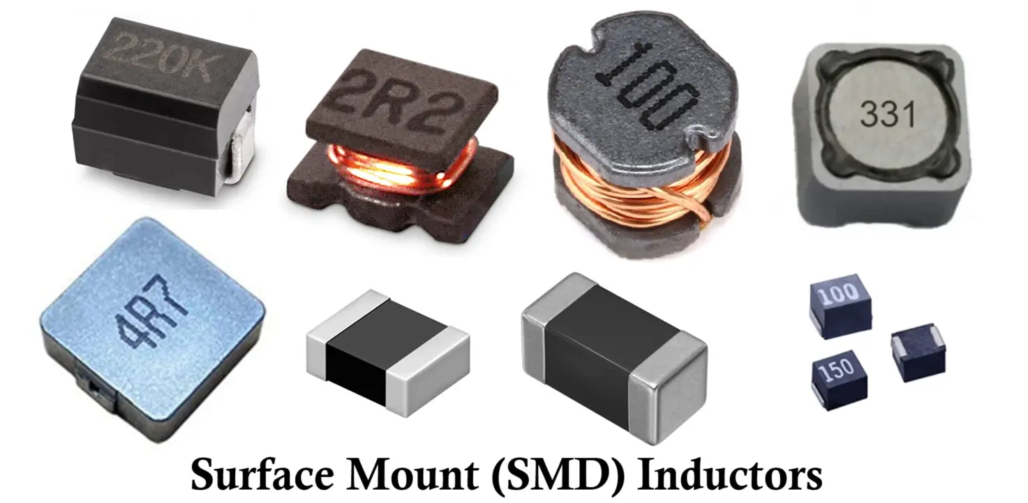
2.6 Surface Mount Inductor (SMD Inductor)
Construction & Working:
A surface mount inductor is designed for SMD technology, optimized for automated PCB assembly. It may be shielded or unshielded, using ferrite or powdered iron cores.
Properties:
- Compact, low-profile design.
- Suitable for high-speed digital and RF circuits.
- Excellent consistency for mass production.
Advantages:
- Space-saving and lightweight.
- High reliability under vibration and shock.
- Compatible with reflow soldering.
Disadvantages:
- Hard to rework manually.
- Slightly higher cost than axial types.
Applications:
- Mobile devices, laptops, and wearable electronics.
- DC-DC converters and EMI filters.
3. Types of Inductors Based on Applications
This category describes inductors by their intended function in electronic circuits — whether for energy storage, noise suppression, or frequency control.
3.1 RF Inductors
Function & Characteristics:
RF inductors operate in radio frequency and microwave bands (MHz to GHz). They are designed to minimize parasitic capacitance and losses to ensure stable performance at high frequencies.
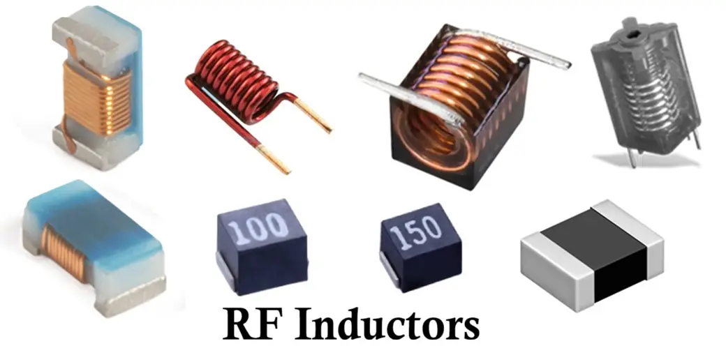
Core Material: Air, ceramic, or ferrite.
Applications:
- RF amplifiers, oscillators, and transmitters.
- Impedance matching networks.
- Wireless communication modules.
3.2 Power Inductors
Function & Characteristics:
Power inductors are designed to store large amounts of energy and handle high current. They are used to prevent voltage spikes, smooth DC outputs, and improve power conversion efficiency in power electronics.
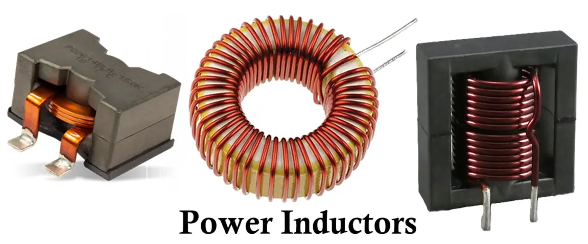
Core Material: Ferrite, powdered iron, or laminated steel.
Applications:
- DC-DC converters, SMPS, and motor drivers.
- Inverters, UPS systems, and EV chargers.
3.3 Filter Inductor (Choke Coils)
Function & Characteristics:
A choke coil blocks high-frequency AC signals while allowing DC or low-frequency current to pass. It “chokes” unwanted noise, harmonics, and ripple in power and signal lines.
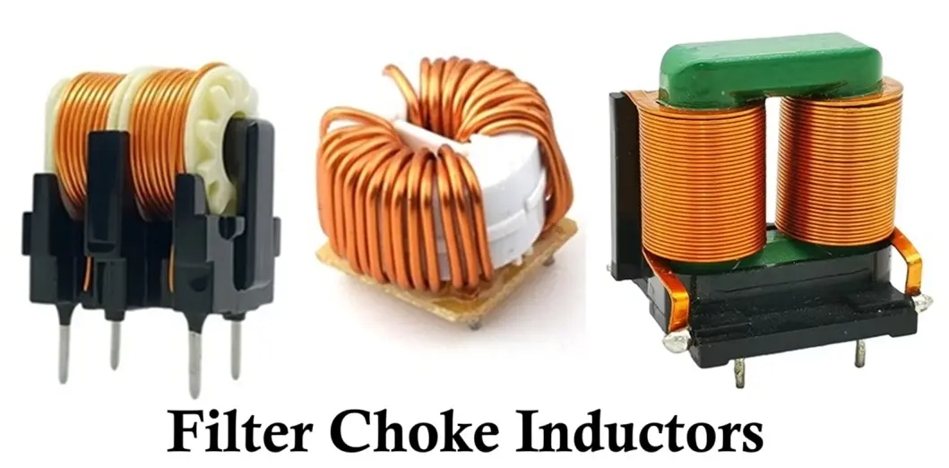
Core Material: Iron, ferrite, or laminated steel.
Applications:
- Power filters and EMI suppression.
- AC-DC rectifier filters.
- Audio and power conditioning circuits.
3.4 Audio Frequency (AF) Inductors
Function & Characteristics:
AF inductors are used in low-frequency (20 Hz–20 kHz) circuits for shaping audio signals. They help in tone control, equalization, and frequency crossover in audio systems.
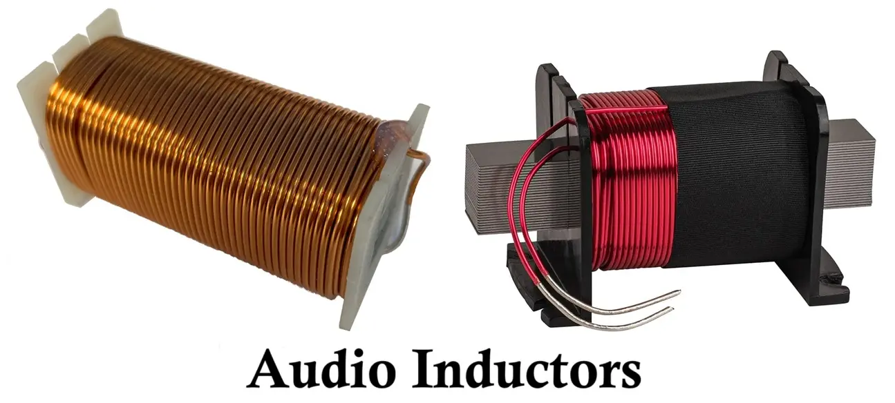
Core Material: Ferrite or laminated iron core.
Applications:
- Loudspeaker crossover networks.
- Audio filters and equalizers.
- Tone control and amplifier circuits.
3.5 Sensing Inductors
Function & Characteristics:
Sensing inductors are used in systems where changes in inductance are detected to measure position, proximity, or current. They are key components in inductive sensors and current measurement devices.
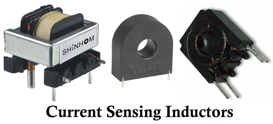
Core Material: Air or ferrite core.
Applications:
- Inductive proximity and position sensors.
- Current sensing circuits and transformers.
- Metal detectors and automotive sensors.
3.6 Pulse Inductors
Function & Characteristics:
Pulse inductors are designed to handle rapid changes in current (pulses) without saturation. They provide energy storage and filtering in high-speed switching and pulse circuits.
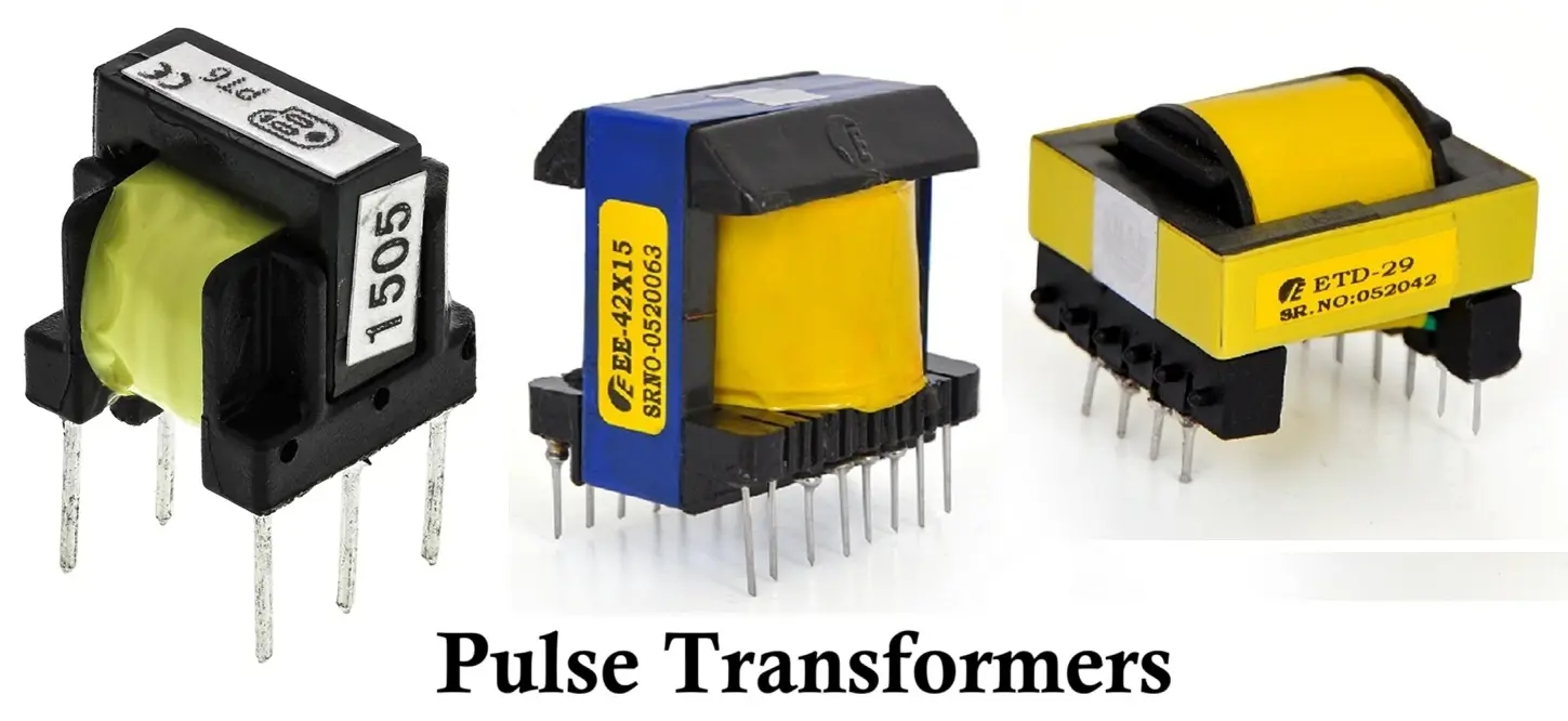
Core Material: Ferrite or powdered iron core.
Applications:
- Switching regulators and PWM controllers.
- Pulse-width modulation circuits.
- Digital and telecommunication systems.
3.7 Coupling Inductors (Transformers)
Function & Characteristics:
Coupling inductors transfer energy between two or more circuits via magnetic coupling. They are used for isolation, signal transfer, and impedance matching.
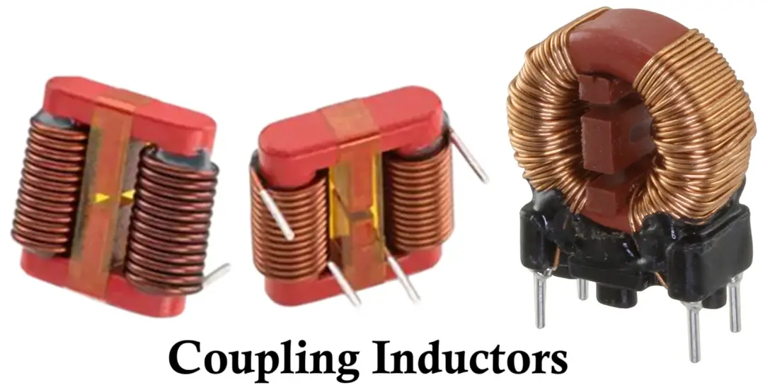
Core Material: Laminated steel or ferrite.
Applications:
- Signal and power transformers.
- Impedance matching networks.
- Isolation and communication systems.
3.8 Variable Inductors
Function & Characteristics:
Variable inductors allow adjustment of inductance by changing the position of a movable core or coil element. This enables fine-tuning of frequency response and resonance in circuits.
Core Material:
Powdered iron, ferrite, or air core.
Applications:
- Tuned circuits in radios and transmitters.
- Frequency modulation and resonance control.
- Adjustable filters and oscillators.
3.9 Molded Inductors
Function & Characteristics:
Molded inductors are compact, encapsulated components where the coil and core are enclosed in a molded insulating material such as epoxy or plastic. The molding provides mechanical protection, environmental sealing, and consistent electrical performance. These inductors are available in both surface-mount (SMD) and through-hole types, commonly used in high-density electronic circuits.
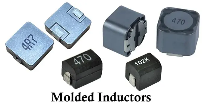
Core Material:
Ferrite or powdered iron core encapsulated in molded resin.
Applications:
- Power supply circuits and DC-DC converters.
- Noise filtering and signal smoothing.
- Portable and consumer electronic devices.
- Automotive and industrial control systems.
Comparison of Inductors
Here is a Comparison table for all the types of inductors showing core material, frequency range and applications.
| Type | Core Material | Frequency Range | Typical Applications |
|---|---|---|---|
| Air Core | None | Very High | RF circuits, antennas, and tuning networks |
| Iron Core | Iron | Low | Power transformers, filters, and audio inductors |
| Ferrite Core | Ferrite | Medium–High | RF circuits, SMPS, and power inductors |
| Laminated Core | Laminated Steel | Low | Power transformers, line chokes |
| Powdered Iron Core | Powdered Iron | Medium | DC-DC converters, switching regulators |
| Toroidal | Ferrite / Powdered Iron | Medium | Power supplies, EMI filters, energy storage |
| Bobbin | Ferrite / Laminated Iron | Medium | Power supplies, filters, choke, coupling |
| Axial | Ferrite / Iron | Low–Medium | Audio filters, signal conditioning |
| Multilayer Chip | Ceramic | High | RF modules, wireless communication |
| Film | Non-magnetic | Very High | Microwave and high-speed circuits |
| Surface Mount (SMD) | Ferrite | Medium–High | Portable and compact electronic devices |
| RF Inductor | Air / Ceramic | High | RF amplifiers, oscillators, and wireless circuits |
| Power Inductor | Ferrite / Iron | Low–Medium | Power converters, inverters, motor drivers |
| Choke Coil | Iron / Ferrite | Low–Medium | EMI suppression, power filters, rectifier circuits |
| Audio Frequency (AF) Inductor | Ferrite / Laminated Iron | Low | Audio filters, speaker crossovers, tone control |
| Sensing Inductor | Air / Ferrite | Low–Medium | Proximity sensors, current sensing, metal detectors |
| Pulse Inductor | Ferrite / Powdered Iron | Medium | Switching regulators, pulse circuits, digital systems |
| Coupling Inductor (Transformer) | Laminated Steel / Ferrite | Low–Medium | Signal transfer, isolation, impedance matching |
| Variable Inductor | Powdered iron/ ferrite/ air core | Medium–High | Tuning, FM, resonance filters & oscillators |
| Molded Inductors | Powdered iron/ ferrite core | Medium–High | Noise filters, power filters, signal conditioning |
Advantages of Inductors
- Efficient energy storage in the form of magnetic fields.
- Smooth current flow by opposing sudden current changes.
- Useful in filtering noise and unwanted signals in AC circuits.
- Provides isolation and coupling in transformers and RF circuits.
- High reliability and long operational life when used properly.
Disadvantages of Inductors
- Bulky and heavy compared to resistors and capacitors.
- Costlier for higher inductance values.
- Energy losses due to core hysteresis and eddy currents.
- Difficult to integrate into ICs due to size and magnetic fields.
- Voltage spikes may occur during sudden disconnection of current.
Applications of Inductors
Here are some of the key applications of inductors:
- Filters – Used with capacitors to create low-pass, high-pass, and band-pass filters in audio and communication systems.
- Transformers – Two magnetically coupled inductors transfer electrical energy between circuits at different voltage levels.
- Chokes – Block AC components while allowing DC to pass in power supply circuits.
- Energy Storage – Store and release energy efficiently in SMPS and DC-DC converters during switching operations.
- Oscillators and Tuned Circuits – Combined with capacitors in LC circuits for frequency generation and selection in radios.
- Filters in Communication Systems – Remove unwanted signals or frequencies in RF and audio applications.
- Inductive Sensors – Used in proximity sensors and metal detectors that detect changes in magnetic fields.
- Relay and Solenoid Coils – Form the magnetic coils that create motion in relays and solenoids.
- Inductive Charging – Enable wireless power transfer through magnetic coupling between coils.
Conclusion
Inductors are vital components in modern electronic and electrical circuits. Their ability to store magnetic energy, filter signals, and resist current changes makes them important.
- Air and Ceramic Core inductors excel in high-frequency precision applications like communication system.
- Ferrite and Powdered Iron Core inductors dominate power electronics due to their efficiency.
- Toroidal, Multilayer, and Surface Mount inductors suit compact, high-performance designs.
- Choke coils and Power inductors ensure noise suppression and energy stability in power systems.
From various types of inductors selection of correct one depends on frequency, inductance, current rating, core material, and physical size. Proper choice enhances circuit efficiency, stability, and electromagnetic compatibility, ensuring reliable performance across a wide range of electronic systems — from micro-scale wireless modules to large-scale industrial power converters.
Types of Resistors with Symbol, Classification and Applications
Types of Capacitors with Symbol, Classification and Applications
Types of Diodes with Symbol, Definition, Working and Applications
Types of Transistors: Classification (BJT, JFET, MOSFET & IGBT)