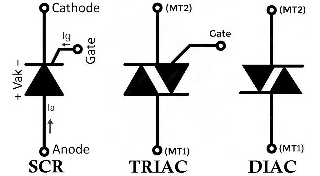
In power electronics, the SCR, DIAC, and TRIAC are three common semiconductor devices that are very useful in electric power control and conversion applications. Though they all belong to the thyristor family, their operation, structure, and applications differ significantly.
Here’s a detailed explanation of SCR (Silicon Controlled Rectifier), DIAC (Diode for Alternating Current), and TRIAC (Triode for Alternating Current)—including their symbol, construction, working principle, advantages, disadvantages, and applications.
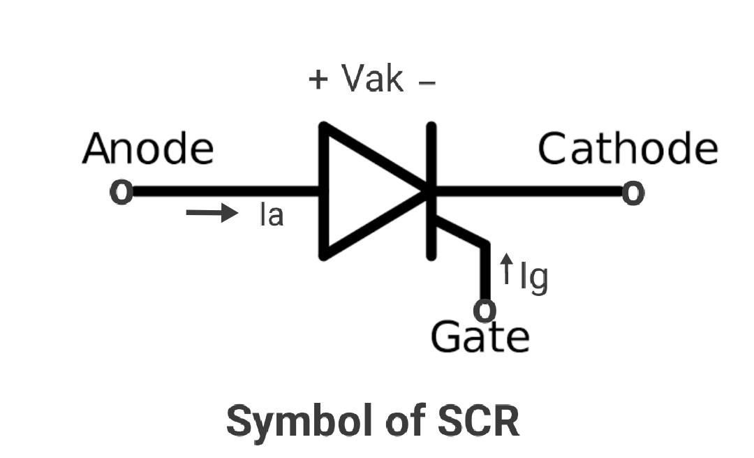
SCR – Silicon Controlled Rectifier
Construction of SCR:
- Layers: Four-layer semiconductor structure — PNPN.
- Terminals: Three terminals — Anode (A), Cathode (K), and Gate (G).
- Junctions: Three junctions present between the P and N layers.
- Doping: Layers are doped alternately to allow unidirectional current flow.
- Package: Usually housed in a sturdy plastic or metal casing for heat dissipation.
- Unidirectional Design: Conducts current only in one direction — anode to cathode.
Working of SCR:
- Forward Blocking Mode: The anode is positive w.r.t. the cathode, but the device remains OFF. Only a tiny leakage current passes due to the reverse-biased junction.
- Triggering Mode: Applying a small positive gate pulse turns the SCR ON. Once triggered, the device latches into the conducting state.
- Forward Conduction Mode: After being triggered, the SCR conducts heavily and stays ON even if the gate signal is removed. It continues conducting until the load current drops below the holding current.
- Reverse Blocking Mode: The anode is negative w.r.t. the cathode, and the SCR behaves like a reverse-biased diode, blocking reverse current.
Advantages of SCR:
- High Power Handling: Can control large voltages and currents, making it suitable for industrial applications.
- Efficient Switching: Acts like a fast switch—once triggered, it stays on until the current drops below a certain value (holding current).
- Gate Control: Can be turned ON by a gate signal; small input controls large output.
- Compact Design: More efficient than mechanical switches or relays.
- Reliable: Robust with a long operational life when used properly.
Disadvantages of SCR:
- Unidirectional Device: Only allows current to flow in one direction—requires additional components to work with full AC waveforms.
- No Automatic Turn-Off in AC: Needs extra circuitry (commutation circuit) to turn off during conduction in AC.
- Sensitive Gate: Improper gate triggering can lead to unwanted conduction.
- Complex Control in AC Circuits: Cannot handle both half-cycles without external design modifications.
Applications of SCR:
- Controlled rectifiers – Convert AC to controlled DC output.
- DC motor speed control – Vary DC motor speed by adjusting power supply.
- Battery chargers – Regulate charging current.
- Phase angle control – Adjust the power delivered to resistive or inductive loads.
- Crowbar circuits – Overvoltage protection in power supplies.
SCR as a Switch, its Advantages, Disadvantages and Applications
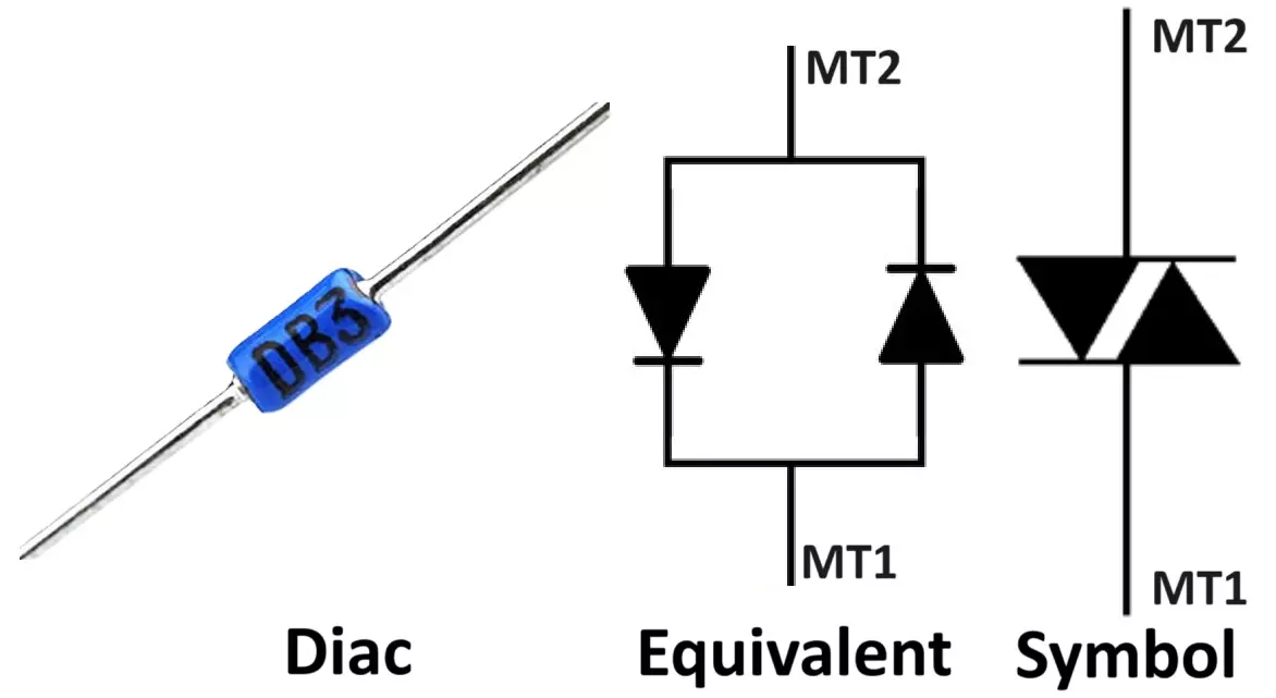
DIAC – Diode for Alternating Current
Construction of DIAC:
- Layers: Consists of a five-layer semiconductor structure — PNPNP or NPNPN — arranged in a symmetrical manner.
- Terminals: Has two main terminals — A1 and A2, and no gate terminal.
- Junctions: Three junctions are present between the P and N layers.
- Symmetrical Doping: The P- and N-type layers on either side of the middle layer have identical doping concentrations, making the device symmetrical.
- Packaging: Typically enclosed in a small, plastic or epoxy package for easy mounting on PCBs.
- Bidirectional Design: The symmetrical structure enables the DIAC to switch on with almost the same breakover voltage in either polarity.
Working of DIAC:
- The DIAC stays OFF until the applied AC voltage reaches its breakover voltage (typically 30–40 V).
- Once this threshold is crossed, it switches ON abruptly and allows current to pass.
- After triggering, it exhibits negative resistance, helping rapid rise of current.
- It is often used to trigger TRIACs symmetrically during both positive and negative halves of the AC cycle.
Advantages of DIAC:
- Bidirectional Conduction: Allows current to flow in both directions after breakdown voltage is reached.
- No Gate Required: Operates automatically; no control signal needed.
- Symmetrical Switching: Breaks down at nearly the same voltage in both directions, providing balanced triggering.
- Compact and Low Cost: Simple to implement in low-power AC control circuits.
Disadvantages of DIAC:
- Not a Power Device: Cannot directly control high loads; used only for triggering.
- No External Control: Once built, breakdown voltage cannot be changed.
- Limited Current Capability: Not suitable for medium or high-power applications.
Applications of DIAC:
- Triggering TRIACs in AC power control.
- Light dimmers – Smooth and flicker-free brightness control.
- Fan regulators – Stepless fan speed control.
- Heater control circuits – Used in thermostatic heating devices.
- Phase control circuits – Provides sharp triggering at precise points.
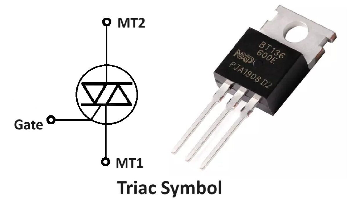
TRIAC – Triode for Alternating Current
Construction of TRIAC:
- Layers: Five-layer semiconductor structure — PNPNP or NPNPN — with symmetrical arrangement.
- Terminals: Three terminals — Main Terminal 1 (MT1), Main Terminal 2 (MT2), and Gate (G).
- Junctions: Three junctions present between alternating P and N layers.
- Symmetrical Doping: Doped symmetrically so that it can conduct in both directions.
- Package: Typically housed in a plastic or epoxy case for easy mounting.
- Bidirectional Design: Conducts AC current in both directions once triggered.
Working of TRIAC:
- Initially stays OFF until a small current is injected into the gate.
- Once triggered, it switches ON and conducts current between MT1 and MT2 in either direction.
- It continues to conduct until the current falls below the holding current at the end of each half-cycle.
- Commonly used in AC power control like lamp dimmers, fan regulators, and motor speed control.
TRIAC Full Form, Symbol, Working, VI Characteristic & Application
Advantages of TRIAC:
- Bidirectional Control: Can conduct during both positive and negative cycles of AC, allowing full-wave power control.
- Single Gate Trigger: Requires only one gate signal to control both directions.
- Compact Design: Replaces two SCRs in anti-parallel configuration.
- Cost-Effective: Saves on component count and simplifies circuit design.
- Good for AC Loads: Ideal for resistive and some inductive AC loads.
Disadvantages of TRIAC:
- Lower Power Ratings than SCRs: Not suited for very high current or voltage without large heatsinks.
- Low Noise Susceptibility: Unintentional triggering by line disturbances or harmonics.
- Snubber Required: For inductive loads, a snubber circuit is often needed to prevent malfunction or false triggering.
- Complex Triggering for Inductive Loads: More sensitive to load type; triggering must be carefully controlled.
Applications of TRIAC:
- Light dimmers – Household and stage lighting.
- Fan speed controllers – AC ceiling or exhaust fans.
- Heater control systems – Electric stoves, room heaters, etc.
- AC motor speed controllers – Washing machines, power tools.
- Electronic switches – Touch-activated or sensor-based switching.
Differences Between SCR, DIAC, and TRIAC
Here is a detailed comparison table of SCR, DIAC and TRIAC
| Parameter | SCR | DIAC | TRIAC |
|---|---|---|---|
| Full Form | Silicon Controlled Rectifier | Diode for Alternating Current | Triode for Alternating Current |
| Terminals | 3 (Anode, Cathode, Gate) | 2 (Terminal 1, Terminal 2) | 3 (MT1, MT2, Gate) |
| Direction of Current | Unidirectional | Bidirectional | Bidirectional |
| Power Handling | High | Low | Moderate |
| Control | Gate-controlled | No gate | Gate-controlled |
| Triggering | Requires positive gate pulse | Exceeds breakover voltage | Gate pulse in either polarity |
| Turn-off Method | Current falls below holding value | Current falls below holding value | Current falls below holding value |
| Construction Layers | 4-layer (PNPN) | 5-layer (Symmetric) | 5-layer |
| Main Use | Controlled rectification | Triggering TRIACs | AC power control |
| Popular Name | BT151 | DB3 | BT136 |
Conclusion
By understanding these devices’ characteristics, you can select the appropriate one based on application requirements such as power control, directionality, and triggering needs.
SCR, DIAC, and TRIAC are indispensable in modern power control circuits. Understanding their differences helps engineers and hobbyists design efficient circuits tailored to specific AC or DC control applications.
- Use SCR when you need unidirectional control in DC or AC rectifiers.
- Use DIAC as a triggering device for symmetric AC control.
- Use TRIAC when you require bidirectional switching for AC applications.
What is Thyristor? Working, Symbol, Construction, Types, Operation, Protection and Applications
IGBT Full Form, Symbol, Construction, Working and Applications