Making a water level indicator and pump controller using Arduino is a very good idea. We can fully automate our water supply system using sensors, electronics, and some programming knowledge. The water pump controller which we are making automatically switches ON and off depending on the level of water. Also, it displays the level of water.

Watch this video
Components required:
- Ultrasonic sensor x 1
- Arduino microcontroller (UNO, Mini, Pro mini)
- LCD display (16 x 2)
- Potentiometer x 1
- BJT (bc547 transistor)
- Resistor 220Ω x 1
- 1kΩ resistor x 1
- DC motor (water pump)
- You can control an AC 230V motor just by adding a 5V relay in the circuit. You can control the relay by BJT (bc547 transistor).
Circuit Diagram:
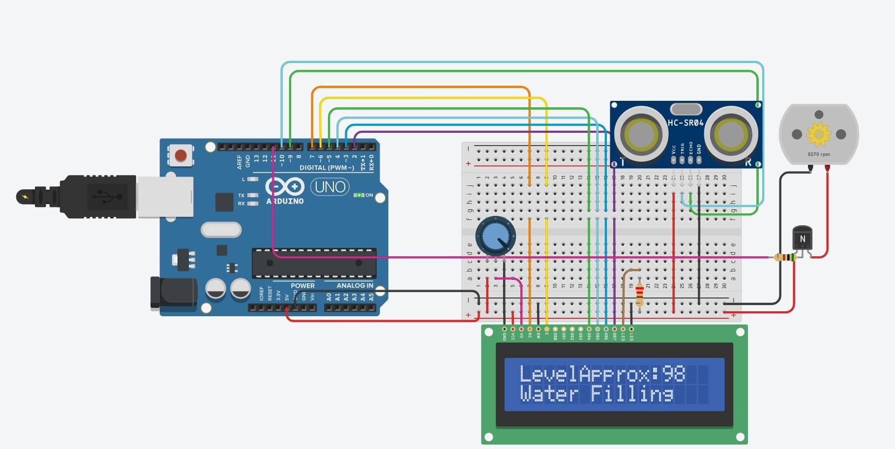
The circuit diagram is as shown in the figure.
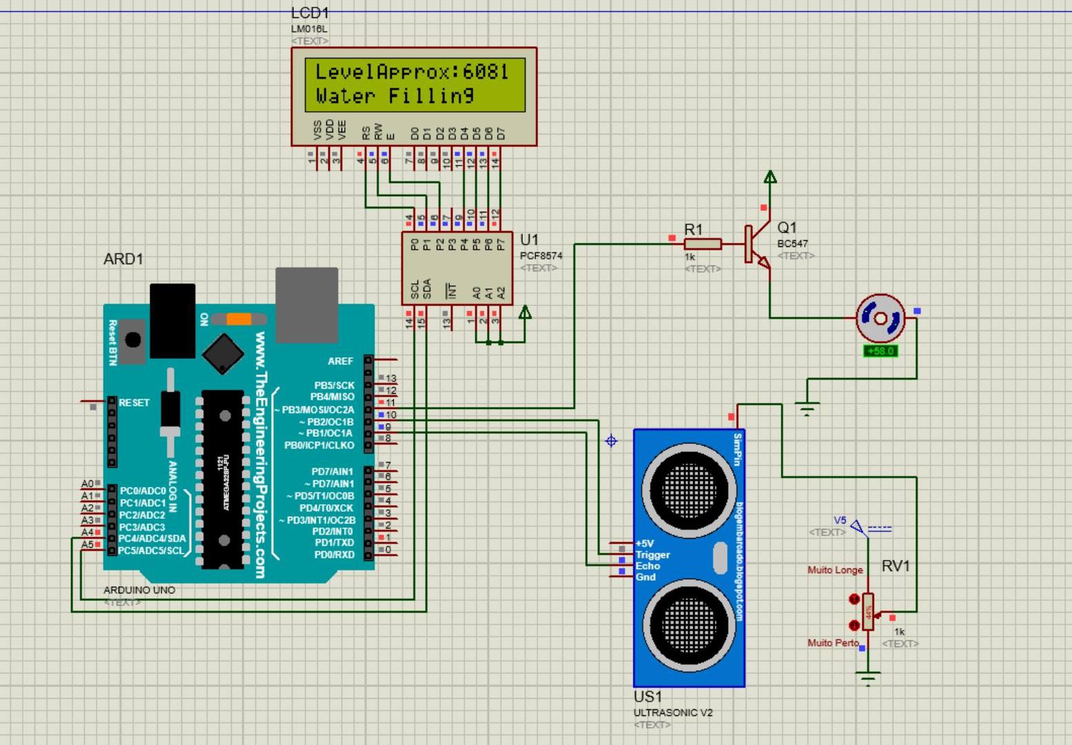
Explanation of circuit:
The ultrasonic sensor is connected to digital input pins of Arduino. Arduino shows the status of motor and water level on the 16 x 2 LCD. If the water level decrease to below 100 centimeters, the motor turns ON. When the level of water becomes more than 40 centimeters microcontroller automatically turns OFF the motor. So there is no wastage of water due to overflow and also it saves electricity by being fully automatic. A potentiometer is used to adjust the brightness of the liquid crystal display. we have used a BJT BC547 to drive the motor, you can use it to drive a relay.
Working of water level indicator using Arduino:
Let’s understand the working of the circuit by code.
#include <LiquidCrystal.h>
#define ECHO 9
#define TRIGGER 10
#define TRIGGER_pulse 1
#define motor 11
int DURATION;
float DISTANCE;
float DIST;
float LED;
LiquidCrystal lcd(7, 6, 5, 4, 3, 2);
int num=1;
In the above code, we have included Library for the liquid crystal display. It is a built-in library. You can also use the I2C liquid crystal library if you have an I2C module for LCD. We have defined Echo, Trigger, and motor pin. Also, we have declared pins for the LCD. The distance value is declared as a float type.
void setup() {
// set up the LCD's number of columns and rows:

pinMode(TRIGGER, OUTPUT);
pinMode(ECHO, INPUT);
pinMode(motor, OUTPUT);
Serial.begin(9600);
lcd.begin(16, 2);
lcd.print("LevelApprox: ");
}
In the void setup loop input and output, pins have been declared. TRIGGER and motor are set as output while ECHO is an input pin. 9600 is the baud rate for serial communications between Arduino and LCD circuit.
void loop() {
digitalWrite(TRIGGER, HIGH);
Trigger is given a logic high input
delay(TRIGGER_pulse);
Delay is given to trigger pin
digitalWrite(TRIGGER, LOW);
Logic high is given to trigger
//see how long it takes to receive the response pulse
DURATION = pulseIn(ECHO,HIGH);
//Distance in centimeters
DISTANCE = 0.01716*DURACION;
//D = ((100-DISTANCE)/100)*255;
DIST = 1.25*DISTANCE;
Serial.println(DISTANCE);

Code to control the motor
if(DIST <= 40){
digitalWrite(11,LOW);
lcd.setCursor(0,1);
lcd.print(" ");
}
if(DIST >=100){
digitalWrite(11,HIGH);
lcd.setCursor(0,1);
lcd.print("Water Filling");
}
printing distance of water level
lcd.setCursor(12, 0);
lcd.print(int(DIST));
delay(1000);
lcd.setCursor(12,0);
lcd.print(" ");
}
#include <LiquidCrystal.h> #define ECHO 9 #define TRIGGER 10 #define TRIGGER_pulse 1 #define motor 11 int DURATION; float DISTANCE; float DIST; float LED; LiquidCrystal lcd(7, 6, 5, 4, 3, 2); int num=1;void setup() { // set up the LCD's number of columns and rows: pinMode(TRIGGER, OUTPUT); pinMode(ECHO, INPUT); pinMode(motor, OUTPUT); Serial.begin(9600); lcd.begin(16, 2); lcd.print("LevelApprox: "); //lcd.setCursor(0,1); //lcd.print(" :"); }void loop() { digitalWrite(TRIGGER, HIGH); delay(TRIGGER_pulse); digitalWrite(TRIGGER, LOW); //see how long it takes to receive the response pulse DURATION = pulseIn(ECHO,HIGH); //Distance in centimeters DISTANCE = 0.01716*DURACION; //LED=((100-DISTANCE)/100)*255; DIST = 1.25*DISTANCE; Serial.println(DISTANCE);if(DIST <= 40){ digitalWrite(11,LOW); lcd.setCursor(0,1); lcd.print(" "); }if(DIST >=100){ digitalWrite(11,HIGH); lcd.setCursor(0,1); lcd.print("Water Filling"); } lcd.setCursor(12, 0); lcd.print(int(DIST)); delay(1000); lcd.setCursor(12,0); lcd.print(" "); }
This is the final code for the water level indicator using Arduino and pump controller.
I hope you enjoyed learning comment down if you have any queries or suggestions.
Dear, I want to purchase Automatic Water level controller, please share price and contact details.
You can get it on amazon or any other website.
In ur circuit diagram,did u use 1k ohm or did u write wrong ohm because I saw 220 ohm in description but not included in the diagram
Thanks for telling
so u use both 1k ohm resistor and why do use 240 v ac?? Isnt DC motor is enough to power water pump. Is only dc motor enought to power water pump if I just use 12 v micro water pump?
Sure you can use it with required modifications in the circuit.
can you explain what is “dist=1.25*dist” and why “distance” is not used in if condiiton?I would be very gratefull if you can reply me as fast as you can
with regards,