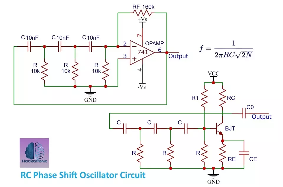
An RC Phase Shift Oscillator Circuit is a type of electronic oscillator that generates sinusoidal signals. It is typically consisting of an amplifier (usually an operational amplifier), resistors, and capacitors arranged in a feedback network. The phase shift network created by the resistors and capacitors causes the output signal of the amplifier to be fed back to its input with a phase shift of 180 degrees at the oscillation frequency. A simpler circuit of phase shift oscillator uses BJT.

RC Phase Shift Oscillator Circuit:
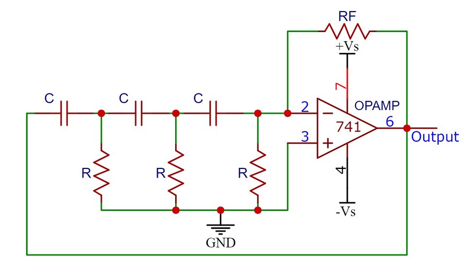
Here is an RC Phase Shift Oscillator a type of electronic oscillator that generates sine waves. It consists of an amplifier (usually an operational amplifier) and a feedback network comprising resistors and capacitors that provide phase shift. Here’s a basic schematic for a simple RC Oscillator using an operational amplifier (op-amp) and a three-stage RC network:
Explanation of RC Oscillator Circuit:
- The operational amplifier amplifies the voltage difference between its two inputs.
- The feedback network (three RC stages) determines the frequency of oscillation by introducing a phase shift.
- The resistors (R) and capacitors (C) are chosen to provide a total phase shift of 180 degrees at the desired frequency of oscillation each stage provides a 60 degree of phase shift.
The general formula for the frequency of oscillation F in a phase shift oscillator is:

Where:
- is the resistance value of each resistor (assuming equal resistance values).
- is the capacitance value of each capacitor (assuming equal capacitance values).
- N is the number of RC stages.
Please note that component values need to be chosen carefully to ensure stability and desired oscillation frequency. Also, it’s essential to consider the limitations and characteristics of the operational amplifier being used. Additionally, component tolerances and variations can affect the oscillation frequency. Experimentation and simulation are often necessary for fine-tuning the circuit.
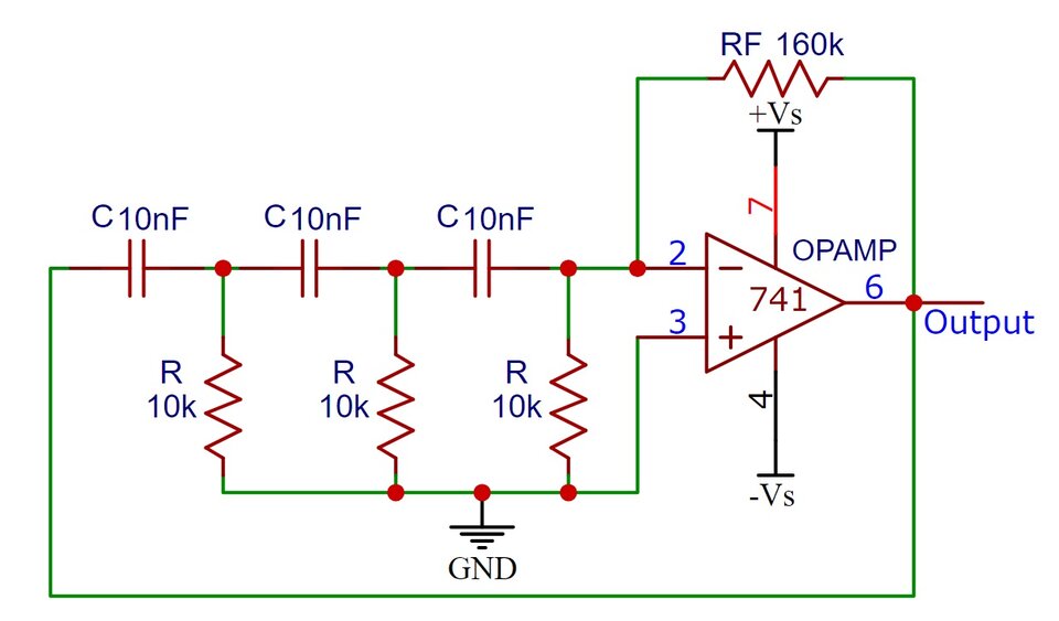
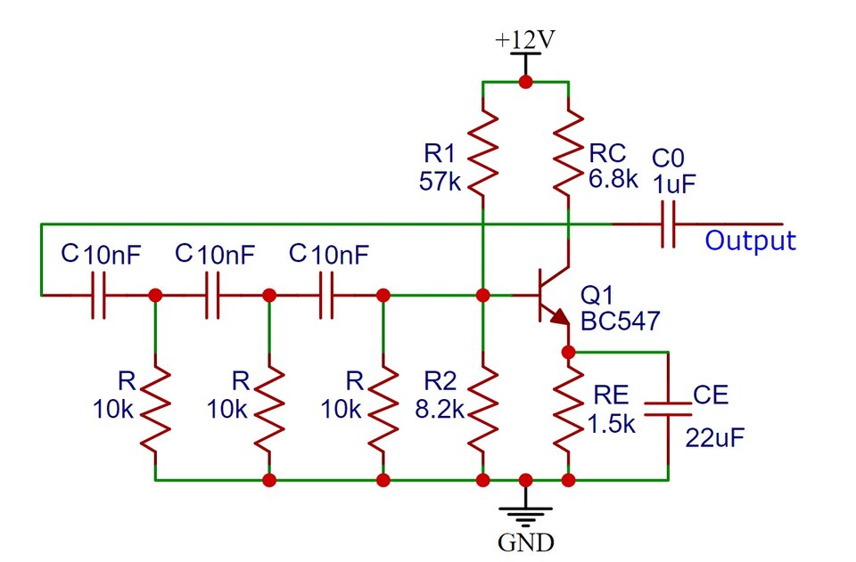
Here is a circuit having output frequency around 650Hz. We have kept value of capacitor 10nF and resistor at 10kΩ.
RC Phase Shift Oscillator Circuit Working:
An RC oscillator is a type of electronic oscillator circuit that generates sinusoidal output signals. It operates on the principle of phase shift, where the phase shift introduced by a network of resistors (R) and capacitors (C) in the feedback path of an amplifier causes positive feedback, leading to sustained oscillations.
Feedback Network:
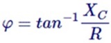
The heart of the RC phase shift oscillator is its feedback network, which typically consists of three identical RC sections connected in series. Each RC section includes a resistor (R) and a capacitor (C). The phase shift introduced by each RC section is approximately 60 degrees (for a high enough frequency) due to the phase relationship between voltage and current in a capacitor and resistor.
Amplifier Stage:
The output of the feedback network is fed into an amplifier stage. This amplifier is usually an operational amplifier (op-amp) configured in an inverting amplifier configuration or a transistor amplifier. The amplifier provides the necessary gain to compensate for the losses in the feedback network and to sustain oscillations.
Phase Shift:
The three RC sections collectively introduce a total phase shift of 180 degrees (3 * 60 degrees) at the desired oscillation frequency. This phase shift, along with the 180-degree phase shift introduced by the amplifier’s inverting nature, results in a total phase shift of 360 degrees (or 0 degrees, which means no phase shift at all). This condition satisfies the Barkhausen criterion for oscillation.
Oscillation:
When the total phase shift around the loop is 360 degrees (or 0 degrees), positive feedback occurs. As a result, the output signal from the amplifier is in phase with the input signal to the feedback network, thus sustaining oscillations.
Frequency Determination:
The frequency of oscillation in an RC oscillator is determined primarily by the values of the resistors (R) and capacitors (C) in the feedback network. The formula for calculating the frequency of oscillation is:
Where:
- F is the frequency of oscillation.
- is the resistance in each RC section.
- is the capacitance in each RC section.
- N is the number of RC stages.
BJT Based Phase Shift Oscillator Circuit:
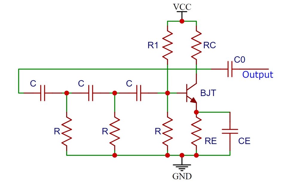
Here is a BJT based phase shift oscillator circuit, in this circuit the OPAMP has been replaced by BJT. The RC network provides a phase shift of 180 degree and the BJT provides remaining 180 degree of phase shift.
BJT Based Phase Shift Oscillator Circuit Example:
Choosing appropriate values for resistors and capacitors ensures stable oscillation at the desired frequency. Typically, equal values for resistors and capacitors are chosen to achieve symmetry in the feedback network.
Overall, the RC phase shift oscillator is a simple and effective circuit for generating sinusoidal signals at a desired frequency. It finds applications in various electronic devices such as signal generators, audio oscillators, and tone generators.
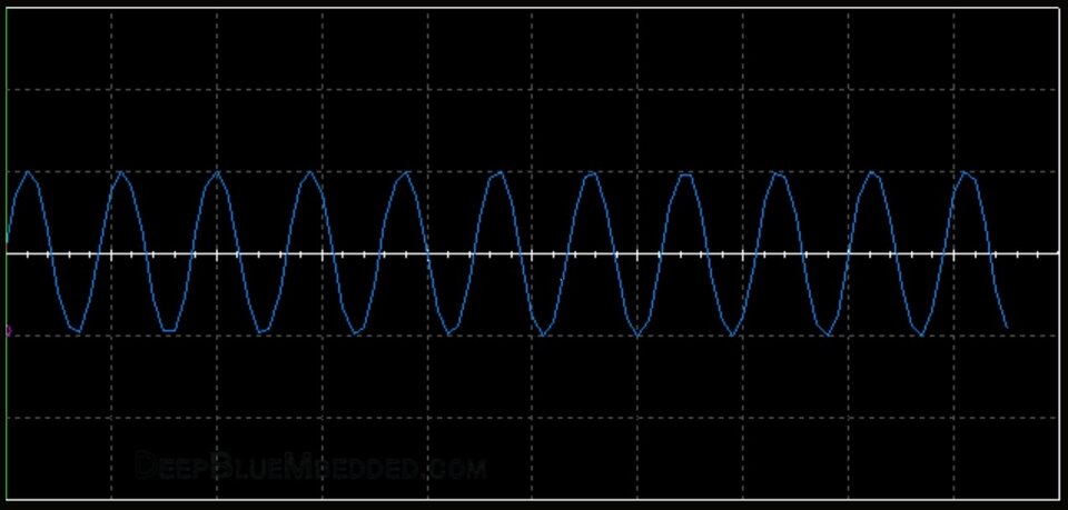
Waveform of RC Oscillator
Applications of RC Phase Shift Oscillator:
RC phase shift oscillators are commonly used in various electronic applications due to their simplicity and effectiveness in generating sine waves at a desired frequency. Here are some typical applications:
Signal Generation:
One of the primary applications of RC phase shift oscillators is to generate continuous sine wave signals at a specific frequency. These signals are utilized in various electronic systems such as audio oscillators, function generators, and tone generators.
Audio Oscillators:
RC phase shift oscillators are frequently employed in audio frequency applications, such as generating tones for musical instruments, audio testing equipment, and sound synthesis.
Frequency Standards:
In some applications, RC phase shift oscillators are used as frequency standards for calibration purposes, especially in low-frequency applications where precision is not critical.
Sine Wave Inverters:
RC phase shift oscillators can be used in sine wave inverters to convert DC power into AC power. Sine wave inverters are used in various applications such as uninterruptible power supplies (UPS), solar power systems, and motor control systems.
Communication Systems:
They are used in communication systems for generating carrier frequencies in radio transmitters and receivers. They can also be used in frequency modulation (FM) and amplitude modulation (AM) circuits.
Medical Devices:
RC phase shift oscillators are used in medical devices such as biofeedback systems, where precise sine wave signals are required for monitoring and treating various physiological conditions.
Test and Measurement Equipment:
They are used in test and measurement equipment for generating reference signals and for frequency calibration purposes.
Educational Purposes:
RC phase shift oscillators are commonly used in educational laboratories to demonstrate the principles of oscillator circuits, frequency generation, and phase shifting.
Instrumentation:
They can be used in instrumentation applications where a stable and precise sine wave signal is needed, such as in data acquisition systems and sensor signal conditioning circuits.
Low-Frequency Applications:
RC phase shift oscillators are particularly useful in low-frequency applications where the complexity and cost of other oscillator circuits, such as LC or crystal oscillators, may be prohibitive.
Overall, RC phase shift oscillators find widespread use in electronics due to their simplicity, versatility, and cost-effectiveness in generating stable sine wave signals across a wide range of frequencies.
Advantages & Disadvantages
The RC Phase Shift Oscillator is a type of oscillator circuit commonly used in electronic devices to generate sinusoidal signals at a specific frequency. Here are some advantages and disadvantages of RC Phase Shift Oscillators:
Advantages of RC Phase Shift Oscillator:
Simple Design: The RC Phase Shift Oscillator circuit consists of only resistors, capacitors, and an active device (such as a transistor or op-amp). This simplicity makes it easy to design and implement.
Low Cost: Since it requires minimal components, the RC Phase Shift Oscillator is relatively inexpensive to build, making it suitable for mass production in consumer electronics.
Stable Frequency: When properly designed, RC Phase Shift Oscillators can provide stable sinusoidal output signals at a fixed frequency determined by the values of the resistors and capacitors in the feedback network.
Wide Frequency Range: With appropriate component values, RC Phase Shift Oscillators can operate over a wide range of frequencies, making them versatile for various applications.
Low Power Consumption: They typically consume low power, making them suitable for battery-operated devices and other low-power applications.
Disadvantages of RC Phase Shift Oscillator:
Sensitive to Component Tolerances: The frequency of oscillation in RC Phase Shift Oscillators is highly dependent on the values of the resistors and capacitors used. Small variations in component values can lead to significant changes in the oscillation frequency, which may require precise component selection or tuning.
Limited Amplitude Stability: The output amplitude of the RC Phase Shift Oscillator may vary with changes in temperature, power supply voltage, and component aging. This limitation can affect the overall stability of the oscillator’s output.
Limited Frequency Stability: While RC Phase Shift Oscillators can provide stable oscillations within a certain frequency range, they may not offer the same level of frequency stability as other oscillator configurations, such as crystal oscillators or voltage controlled oscillators (VCOs).
Limited Output Power: RC Phase Shift Oscillators typically have limited output power compared to other oscillator configurations. This limitation may restrict their use in applications that require higher output power levels.
Frequency Drift: Due to factors such as temperature variations and aging of components, the frequency of oscillation in RC Phase Shift Oscillators may drift over time, requiring periodic calibration or adjustment to maintain accuracy.
Overall, while RC Phase Shift Oscillators offer simplicity and low cost, they may not be suitable for applications that require extremely high frequency stability or precise control over output characteristics. However, for many general-purpose applications, they provide a practical solution for generating sinusoidal signals.