An Astable Multivibrator is an essential oscillator circuit in electronics, used to generate continuous square wave signals without any external triggering. It is called “astable” because it has no stable state — both transistors in the circuit keep switching ON and OFF alternately, producing a continuous flip-flop output.
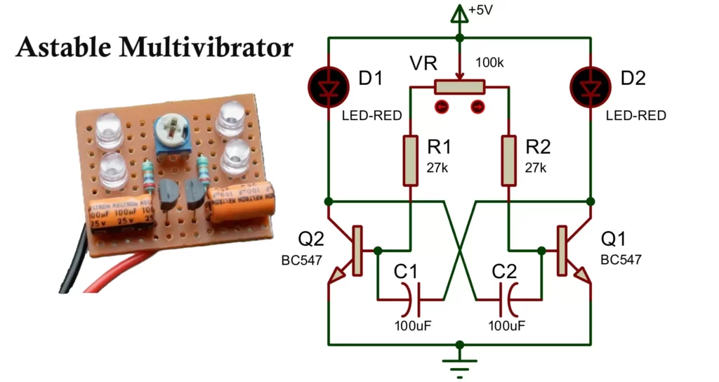
In this article, we will explore a practical astable multivibrator circuit that uses two LEDs, BC547 transistors, 100µF capacitors, 27K resistors, and a 100K potentiometer, making it an excellent visual demonstration for beginners.
Multivibrator Circuit Diagram
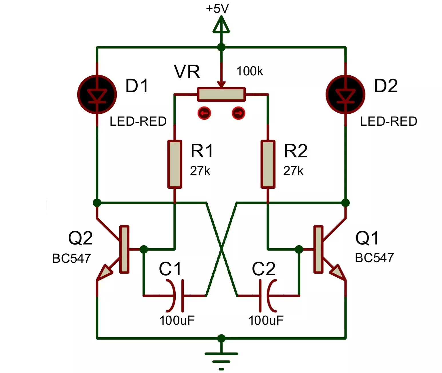
LED1 and LED2 are connected to the collector of BC547 transistors. The emitters of both transistors are connected to the ground.
Components Required
- Transistors: 2 × BC547 NPN
- Resistors: 2 × 27KΩ
- Potentiometer: 1 × 100KΩ (for timing adjustment)
- Capacitors: 2 × 100µF (electrolytic)
- LEDs: 2 × (Any color)
- Power Supply: 3.7V Li-ion battery or DC power source
- Breadboard or PCB for assembly
Astable Multivibrator Construction and Working
1. Circuit Configuration
- Two NPN BC547 transistors are arranged in a cross-coupled manner.
- The collector of each transistor is connected to one LED in series.
- The base of each transistor is connected to the opposite transistor’s collector through a 100µF capacitor.
- Two 27K resistors are connected between the positive supply and each collector (through LED).
- A 100K potentiometer acts as a variable resistor to fine-tune the timing cycle.
2. How Astable Multivibrator Works
- When power is applied, both transistors try to turn ON, but due to component tolerances and capacitor charging, one transistor turns ON slightly faster.
- Capacitor Control:
- The voltage on the left side of C2 controls transistor Q1.
- The voltage on the right side of C1 controls transistor Q2.
- Q1 Turns ON:
- When transistor Q1 turns ON, its collector voltage drops.
- This low voltage is passed through capacitor C1 to the base of Q2, turning Q2 OFF.
- Capacitor Charging:
- With Q2 OFF, capacitor C1 starts charging through the connected 27kΩ resistor.
- The voltage at Q2’s base slowly increases.
- Q2 Turns ON:
- When the voltage at Q2’s base becomes high enough, Q2 turns ON.
- This causes Q2’s collector voltage to drop.
- Q1 Turns OFF:
- The drop at Q2’s collector is passed through capacitor C2 to the base of Q1, turning Q1 OFF.
- Now, C2 begins charging.
- Cycle Repeats:
- The transistors continue switching ON and OFF alternately.
- This creates a continuous oscillation, making the connected LEDs blink one after the other.

Frequency of Multivibrator Circuit
The frequency of oscillation depends on the values of resistors, capacitors, and the potentiometer:
T = 1/(1.1×R×C)
Where T is the time period of one cycle, R is the resistance (27K + potentiometer value), and C is the capacitance (100µF).
Waveform
The circuit produces a square wave output at the collector terminals of the transistors. The voltage toggles between high and low levels at regular intervals, which can be seen as blinking LEDs in this setup.
Advantages of Multivibrator
- Simple Design: Very easy to build using basic components.
- No External Clock: Self-triggered; doesn’t need an input signal.
- Adjustable Frequency: Using the potentiometer allows real-time control over the blinking speed.
- Visual Feedback: LEDs help in understanding the operation clearly.
Disadvantages of Multivibrator
- Not Precision Oscillator: Frequency is sensitive to component tolerances.
- Temperature Drift: Components like capacitors and resistors can drift with temperature.
- Limited Current Output: Cannot drive high-power loads directly.
- Symmetry Limitations: Perfectly symmetrical operation may not be possible with discrete components.
Applications of Multivibrator
- LED Flashers: Decorative lighting, indicators.
- Pulse Generation: Producing timing signals for sequential circuits.
- Tone Generation: If connected to speakers, it can produce a tone.
- Clock Pulse Source: For digital circuits and counters.
- Light Chasers: When used with more stages and delay circuits.
- Educational Demonstrations: Excellent for teaching transistor switching behavior and multivibrator principles.
Modifications and Enhancements
- Changing Frequency: Use different capacitor or resistor values.
- More LEDs: Add more stages to create a running light or chaser.
- Microcontroller Trigger: Can be used as a test input for MCUs.
- MOSFET Upgrade: For higher efficiency or load handling, use MOSFETs in place of BJTs.

Conclusion
The Astable Multivibrator is a classic and foundational circuit in electronics. This simple design using BC547 transistors, LEDs, capacitors, and resistors demonstrates fundamental transistor switching action and oscillator principles in an easy-to-understand and visually appealing way.
Its wide range of applications and ease of construction makes it a favorite project for students, hobbyists, and educators alike.
3 Simple IR Proximity Sensor Circuits with Working & Applications