In this article, we will explore the working of a 5V to 12V boost converter circuit using the XL6009 IC. Boost converters are widely used in electronics to step up voltage from a lower level to a higher one. Among the popular buck-boost converter ICs, the XL6009 stands out for its efficiency, versatility, and affordability.
Features of XL6009 IC

The XL6009 is a 5-pin high-performance, wide-input range buck-boost switching regulator IC. It is capable of stepping up input voltages ranging from 3V to 32V to output voltages as high as 35V. With a switching frequency of 400 kHz and an integrated 4A switch, the XL6009 is an excellent choice for low-power and medium-power applications. Key features of the XL6009 include:
- Wide input voltage range: 5V to 32V
- Adjustable output voltage: 5V to 40V
- High efficiency: Up to 94%
- Built-in 4A switch
- 1.25V reference voltage
- Fixed 400 kHz switching frequency
- Thermal shutdown and overcurrent protection
Applications of the XL6009 Boost Converter
- USB-powered devices requiring higher voltages
- Battery-powered devices
- LED drivers
- Solar charging systems
- Automotive electronics
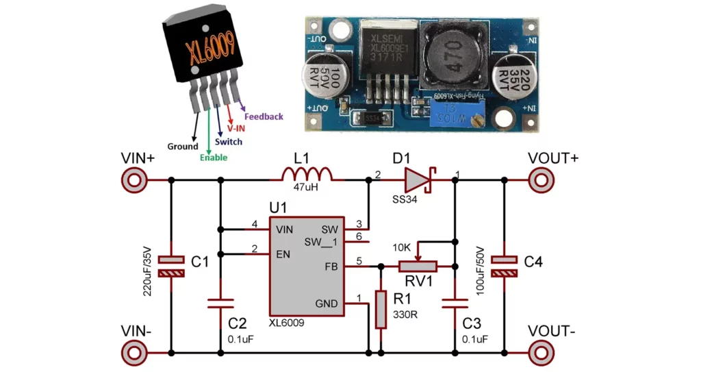
XL6009 Boost Converter Circuit Diagram
Below is the detailed description of the components required for a 5V to 12V boost converter circuit using the XL6009:
| Component | Specification |
|---|---|
| XL6009 IC | Buck-Boost converter IC |
| Inductor (L1) | 47/33µH |
| Diode (D1) | Schottky diode (e.g., SS34) |
| Capacitor (C1) | 220µF, 35V (input side) |
| Capacitor (C4) | 100µF, 50V (output side) |
| Capacitor (C2, C3) | 0.1uF |
| Resistors (R1) | 330Ω |
| Potentiometer (RV1) | 10kΩ for adjustable output |
| Heat sink | Optional for high loads |

Working of XL6009 Boost Converter Circuit
- Input Stage: The XL6009 receives a 5V DC input. The input capacitor (C1) smoothens any voltage ripples and ensures stable operation.
- Inductor and Switching: The XL6009’s internal MOSFET switch drives the inductor (L1). When the switch is ON, the inductor stores energy in its magnetic field. When the switch is OFF, the inductor releases this energy, causing the voltage to rise.
- Diode and Output Capacitor: The Schottky diode (D1) prevents backflow of current and directs the boosted voltage to the output capacitor (C4). The capacitor filters and stabilizes the output voltage.
- Feedback and Regulation: The resistive feedback network (R1 and RV1) monitors the output voltage and feeds it back to the IC. The XL6009 adjusts the duty cycle of its internal switch to maintain the desired output voltage.
Calculating Resistor Values for 12V Output
The output voltage (Vout) is set using the feedback resistors R1 and potentiometer RV1. The formula for output voltage is:
Vout = Vref × (1 + R2 / R1)
Reference voltage of XL6009 is 1.25V
For a 12V output set RV1 to nearly 2.8kΩ.
Practical Tips for Implementation
- Inductor Selection: Choose an inductor with a high saturation current rating (greater than 4A) to prevent core saturation.
- Schottky Diode: Use a diode with a low forward voltage drop and sufficient current rating.
- Capacitor Selection: Use low ESR (Equivalent Series Resistance) capacitors to reduce ripple.
- PCB Design: Minimize trace lengths to reduce losses and EMI (Electromagnetic Interference).
- Heat Dissipation: Add a heat sink to the XL6009 if operating under high load conditions.
Testing and Troubleshooting
- Check Input Voltage: Ensure the input voltage is stable and within the specified range.
- Verify Output Voltage: Measure the output voltage with a multimeter and adjust the potentiometer if required.
- Inspect Waveforms: Use an oscilloscope to observe the switching waveforms and ensure proper operation.
- Monitor Temperature: Check for overheating of the IC and components under load.
Advantages of Using XL6009 IC
- High efficiency reduces power loss.
- Compact and cost-effective solution.
- Adjustable output voltage for versatile applications.
- Integrated protection features enhance reliability.
Conclusion
The XL6009 is a reliable and efficient IC for designing boost converter circuits. By following the guidelines in this article, you can build a 5V to 12V boost converter suitable for various applications. With proper component selection and careful assembly, the circuit will deliver stable and efficient performance. Whether you’re powering an LED array, charging a battery, or running a small motor, the XL6009 boost converter is an excellent choice for stepping up voltage.