An H-bridge motor driver is a versatile circuit that allows a DC motor to rotate in both forward and reverse directions. It is widely used in robotics and motor control applications. This article outlines how to build an H-bridge motor driver circuit using IRFZ44N MOSFETs as the main switching elements, BC547 transistors for driving the complementary MOSFETs, and the required resistors and switches (S1 and S2) to control motor direction.
Circuit Components
IRFZ44N MOSFETs: (4x) These N-channel MOSFETs serve as the main switches for driving the motor.
BC547 Transistors: (2x) Small-signal NPN transistors used to drive the complementary MOSFET switches.
Resistors:
Base resistors: 10kΩ (2x) for the BC547 transistors.
Pull-up resistors 1kΩ (2x) and pull-down resistors 10kΩ (2x) to ensure proper gate voltage when switches are open.
Switches: S1 and S2: Two SPST (Single Pole Single Throw) switches to control the H-bridge.
DC Motor: The load to be driven.
Power Supply: A suitable DC voltage source (e.g., 12V).
H-Bridge Configuration
An H-bridge circuit consists of four switches (in this case, four IRFZ44N MOSFETs) arranged in an “H” shape. The motor is connected between the two midpoints of the H-bridge. Here’s how the switches are configured:
High-Side MOSFETs:
Q1 and Q3 are connected to the positive terminal of the power supply.
Their sources are connected to the motor terminals.
Low-Side MOSFETs:
Q2 and Q4 are connected to the negative terminal (ground).
Their drains are connected to the motor terminals.
Driving Circuit:
BC547 transistors drives gate of Q1 and Q3, allowing control of high-side MOSFETs.
S1 and S2 control the base of the BC547 transistors with gates of Q2 and Q4 MOSFETs.
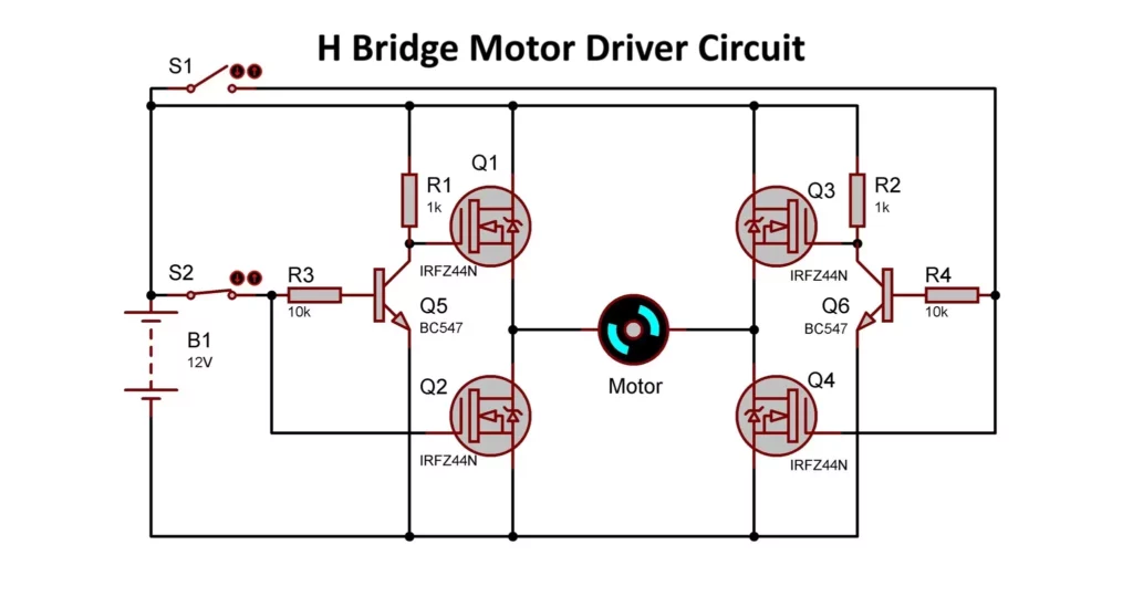
H Bridge Motor Driver Circuit Diagram

Working of H Bridge Motor Driver
- Forward Rotation:
- S2 close S1 open: This turns on Q5, which turns OFF Q1, stopping the conduction and leaving Q3 in ON State.
- Q2 is turned ON directly via its gate.
- Q2 and Q3 complete the circuit, allowing current to flow through the motor in one direction.
- Reverse Rotation:
- S1 close S2 open: This turns on Q6, which turns OFF Q3, stopping the conduction and leaving Q1 in ON State.
- Q4 is turned ON directly via its gate.
- Q1 and Q4 complete the circuit, allowing current to flow through the motor in the opposite direction.
- Stopping the Motor:
- Both switches (S1 and S2) are open, leaving both lower MOSFETs OFF and breaking the circuit. Don’t keep both pins high.
Advantages of This Configuration
- Cost-Effective: Using IRFZ44N and BC547 components ensures affordability.
- Efficient Switching: The MOSFETs have low RDS(on), reducing power loss.
- Protective Features: Flyback diodes safeguard the MOSFETs from back EMF.
- Simple Control: Manual switches make the circuit easy to understand and debug.
Applications
- Robotics: Driving DC motors for robots or automated vehicles.
- Conveyor Belts: Controlling direction and speed.
- DIY Projects: Educational projects involving motor control.
Here are two very popular motor driver ICs. Instead of using complex circuit, you can use them in your project.
L298N Motor Driver
- A dual H-Bridge motor driver IC capable of controlling two DC motors simultaneously in both forward and reverse directions.
- Features high current capability (up to 2A per channel) and supports motors with voltages from 5V to 35V.
- Includes built-in protection diodes and a 5V voltage regulator for powering logic circuits.
- Widely used in robotics, DIY projects, and motor control applications.
L293D Motor Driver
- A quad half-H-Bridge motor driver IC designed to control two DC motors or a stepper motor.
- Handles up to 600mA per channel with a supply voltage range of 4.5V to 36V.
- Includes built-in flyback diodes for motor protection and is known for its simplicity and affordability.
- Ideal for low-power applications like small robotics or toy motor control.
Both ICs are versatile and commonly used in projects requiring basic motor control functionality.
By combining IRFZ44N MOSFETs, BC547 transistors, and a simple switching mechanism, this H-bridge motor driver circuit is a practical and efficient solution for controlling DC motors in various applications.