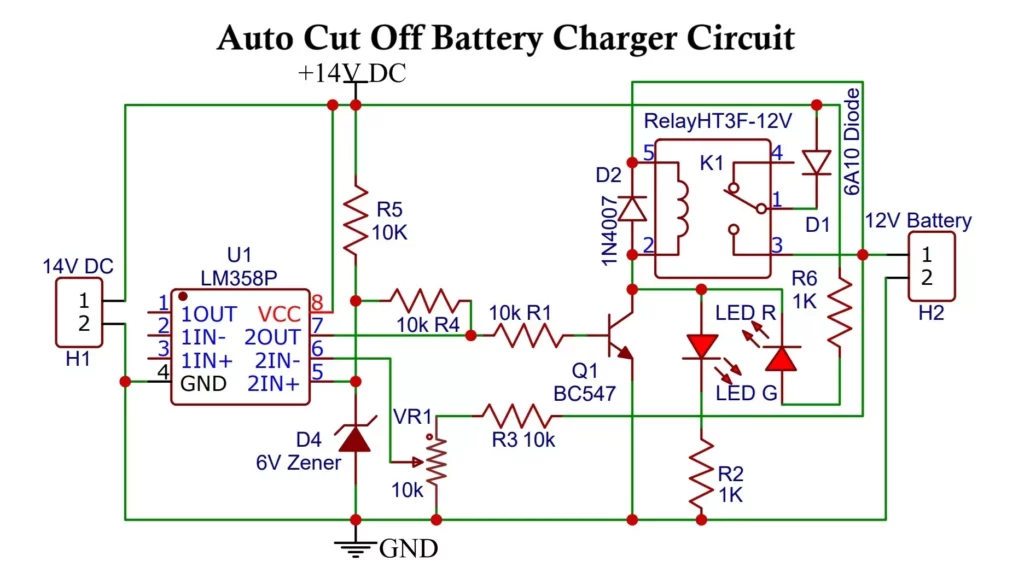
Automatic battery charger circuit:

Battery Charger Components:
- R1, R3, R4, R5 10k, R2, R6 1K (1/4watt)
- VR1 10k potentiometer
- HT3F-12V Relay
- D1 6A10 Diode
- D2 1N4007
- D4 1N5233B (6V Zener)
- Q1 BC547
- U1 LM358
- LED G (green)
- LED R (red)
- 12V battery
- 2 pin PCB screw terminal 2
Working of automatic battery charger circuit:
First of all, the 220V AC is stepped down by transformer to 15V. Then it is rectified and smoothen by capacitor C1. It is regulated to 14V by using voltage regulator Lm317. Then it is fed to the battery charging circuit. To set the threshold voltage also called as cut off voltage for Battery charging, LM358 and potentiometer VR1 (or trimmer) have been used.
We apply a reference voltage on the non-inverting pin of LM358. The threshold voltage is applied at the inverting pin of the opamp. If Battery charges up to threshold voltage, opamp will turn OFF the transistor which acts as a switch and relay will be de-energized. This turns off battery charging process. the upper threshold voltage of Lead acid battery is 12.8V and lower threshold voltage is 11.5V.
This happens as the battery charges to the set threshold potential, the voltage at inverting pin of OPAMP becomes higher than non-inverting pin. The output of OPAMP becomes low which turns OFF transistor making relay OFF. This cuts power supply to the battery. If there is a high input voltage the Zener diode breaks to protect circuit.
LED Indication:
During the charging process, Red LED glows which indicates that the battery is charging. When the battery gets fully charged its voltage reaches the threshold voltage, this voltage changes the output of the OP-AMP to low. This changes the position of the relay to switch off the circuit Green LED will glow pointing to the completion of charging. Both the LEDs are connected in such a way that only one LED will glow at a time due to posit or negative voltage present at collector terminal of BC547 transistor. If you have more powerful relay, use more powerful transistor.
How to set the battery cutoff threshold:
Initially keep the power to the circuit switched OFF.
Connect a variable DC power supply source across the battery points of the circuit.
Apply a Voltage that equals to the cutoff threshold voltage of the battery. Then adjust RV1 so that relay just activates, that is the cut-off voltage.
For a 12V battery, it is nearly 13V and for a Li-Po battery, it is 4.35V.
To charge Li-Po battery you can use this 5V charger circuit.
The setting up of the circuit is done.
Remove the external variable voltage source and replace it with a battery for charging purposes.
Variable Power Supply Circuit:

The above circuit is a variable power supply circuit. This circuit can give an output voltage ranging from 1 or 2 to 37 volts and an output current up to 1.5A. you can use the above circuit to make a variable power supply.
Working of the circuit:
The transformer used in the above circuit is having a 15V, 3A output. Then we have used the KBPC3510 rectifier to rectify the AC output of transformer. The rectifier converts Sinusoidal AC into a unidirectional DC pulsating Voltage having AC component and fluctuations.
A 1000uf polar capacitor is used to smooth out the DC supply. After this, by using IC LM317 the DC output is controlled. By using the 10k potentiometer the output DC voltage can be controlled. Further, the 10uf cap is used for a varying load.
Components:
- T1 15V Transformer (3A)
- KBPC3510 Bridge diode
- C1 1000uF (25V electrolytic)
- C2 10uF (non-polar)
- R1 220Ω
- VR 10kΩ
- LM317 IC