In this guide, we will dive deep into BMS circuit diagram for 1S, 2S, 3S, and 4S Li-ion battery configurations, providing detailed explanations of its components and functionality.
Lithium-ion batteries are indispensable in modern technology, powering everything from portable electronics to electric vehicles. However, their sensitive nature requires precise charging and discharging management to ensure safety, longevity, and efficiency.
This is where a Battery Management System (BMS) becomes crucial. A well-designed BMS circuit can prevent overcharging, over-discharging, and short circuits, while also balancing individual cells in a battery pack.
1. Introduction to BMS and Its Importance
Lithium-ion batteries are popular due to their high energy density and lightweight properties. However, they are prone to damage and hazards if mishandled. Overcharging can cause swelling, overheating, or even explosions, while deep discharges can permanently degrade the battery. A BMS ensures:
- Controlled charging and discharging.
- Voltage and current stabilization.
- Cell balancing to maintain uniform voltage across cells.
- Protection against overvoltage, undervoltage, and short circuits.
- Enhanced safety and extended battery life.
By implementing a BMS circuit, you can maximize the performance and longevity of your lithium-ion batteries while minimizing the risk of accidents or malfunctions. You can also make a Battery voltage level indicator for your Li-ion battery pack.
2. Understanding the Key Components of a BMS Circuit
- A. Battery Management Unit (BMU)
- B. Voltage Balancing Circuit
- C. Temperature Monitoring
- D. Current Sensing and Control
- E. Protection Circuits
A. Battery Management Unit (BMU)
The BMU is the brain of the BMS circuit, responsible for monitoring individual cell voltages and states of charge (SOC). It ensures:
- Real-time voltage monitoring of each cell.
- Data collection for charging and discharging decisions.
- Prevention of voltage imbalances that could harm the battery pack.
B. Voltage Balancing Circuit
Voltage balancing ensures uniform voltage across all cells in a series-connected battery pack. Two types of balancing techniques are employed:
- Passive Balancing: Excess energy from overcharged cells is dissipated as heat using resistors.
- Active Balancing: Energy is redistributed from overcharged cells to undercharged ones, improving efficiency.
C. Temperature Monitoring
Temperature sensors monitor the thermal state of the battery pack. This prevents thermal runaway and ensures optimal operating conditions. Common sensors include thermistors and thermocouples.
D. Current Sensing and Control
Current sensing measures the flow of charge during charging and discharging. Using current sensors and shunt resistors, the circuit regulates the current to:
- Prevent overcharging.
- Avoid over-discharging.
- Enhance battery efficiency.
E. Protection Circuits
Protection circuits safeguard the battery pack against potential hazards:
- Overvoltage Protection: Disconnects the charger when a cell reaches its maximum voltage (e.g., 4.2V for Li-ion cells).
- Undervoltage Protection: Disconnects the load to prevent deep discharge.
- Short-Circuit Protection: Immediately interrupts the circuit in case of a short.
These components work together to ensure the safe and efficient operation of the battery pack, extending its lifespan and reliability.
3. Designing 1S, 2S, 3S, 4S BMS Circuit for lithium-Ion Batteries
Let’s understand how to make 1S, 2S, 3S, 4S BMS Circuits for Li-Ion batteries.
1S BMS Circuit Diagram for Lithium Ion Battery
This is a simple circuit which can manage single Li-ion battery at 4.2V. For making a 2S, 3S and 4S BMS you only need to connect These BMS circuits in series.
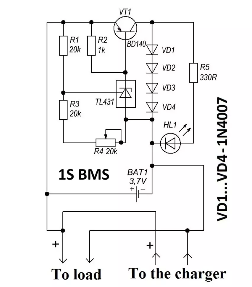
Components:
- TL431 Zener diode
- BD140 PNP transistor
- LM317 regulator (voltage and current mode)
- 1N4007 diodes (4x)
- LED indicator
- 20K potentiometer
Working Principle:
- The TL431 Zener diode sets the cutoff voltage (e.g., 4.2V).
- The transistor and 4 diodes make an alternate path for current when the battery reaches its threshold voltage (4.2V set by potentiometer), protecting it from overcharging.
- LM317 regulates the input voltage and current, ensuring safe charging conditions.
3S BMS Circuit Diagram for Lithium-Ion Batteries
3S Battery Management System (BMS) circuit for lithium-ion batteries. The 3S configuration is a series connection of three cells, requiring a robust BMS to ensure balanced charging, overcharge protection, and efficient power delivery. We’ll focus on a straightforward yet highly effective design using the TL431 Zener diode, BD140 PNP transistor, LM317 regulator, 1N4007 diodes, LED indicators, and 20K potentiometers.

Components Required:
- TL431 Zener Diode (3 units): Acts as a voltage regulator to set the cutoff voltage for each cell.
- BD140 PNP Transistor (3 units): Enables current bypass to protect against overcharging.
- LM317 Regulator (2 unit): Provides stable input voltage and current.
- 1N4007 Diodes (12 units): Used in bypass and protection circuits.
- LED Indicators (3 units): Signals the charging status of each cell.
- 20K Potentiometer (3 units): Allows precise adjustment of the cutoff voltage for individual cells.
Working Principle of the Circuit
- Voltage Regulation with TL431: Each TL431 Zener diode is configured to regulate the voltage for one battery cell. It sets the cutoff voltage, typically 4.2V for lithium-ion cells, ensuring the cell does not overcharge.

TL431 voltage regulator - Bypass Protection with BD140 and Diodes: When a cell reaches the threshold voltage, the BD140 transistor and four 1N4007 diodes form a bypass pathway for the current. This prevents further charging of the fully charged cell while allowing the other cells to continue charging.
- Input Voltage and Current Regulation with LM317: The LM317 regulator stabilizes the input voltage and current, ensuring that the charging process is safe and consistent for the entire battery pack.


Circuit Design for 3S Configuration
1. Voltage Regulation Circuit for Each Cell
- Connect the TL431 Zener diode in parallel with the cell.
- Use the 20K potentiometer to fine-tune the cutoff voltage for the cell (4.2V).
- Attach an LED indicator to the circuit to signal when the cell reaches its full charge.
2. Bypass Circuit Assembly
- Place the BD140 PNP transistor in series with the TL431.
- Add four 1N4007 diodes in the collector circuit of the BD140. These diodes form a dummy load, dissipating excess power as heat.
- Ensure proper heat dissipation by attaching heat sinks to the transistors.
3. LM317 Voltage and Current Regulation
- Configure the LM317 to provide a stable output voltage matching the total series voltage of the 3 cells (e.g., 12.6V for 3 × 4.2V).
- Set the desired current limit by adjusting the resistor values in the LM317 circuit. Use an online LM317 calculator to determine resistor values for your required current.
4. Integrating Three Circuits
- Repeat the voltage regulation and bypass circuit assembly for all three cells.
- Connect the three circuits in series, ensuring proper polarity between cells.

Testing and Calibration of BMS Circuit
Voltage Calibration:
Use a precise power supply to simulate a 4.2V input for each cell. Adjust the potentiometer for each TL431 circuit until the LED lights up, signaling the cutoff voltage is reached.
Current Testing:
Measure the current through each cell using a multimeter to ensure uniform charging.
Balancing Test:
Verify that the bypass circuit activates for fully charged cells, allowing others to continue charging.
Thermal Check:
Monitor the heat generated by the transistors and diodes during operation. Add additional heat sinks if necessary.
Optimize the BMS circuit for efficiency, reliability, and safety. Conduct thorough testing to identify and rectify any issues before deploying the circuit in real-world applications. Watch this video for better understanding.

Advantages of BMS Circuit
- Cost-Effective: Uses readily available components like TL431 and BD140.
- Simple Configuration: The design is straightforward, making it ideal for DIY enthusiasts and small-scale applications.
- Efficient Balancing: Ensures that all three cells are balanced during charging.
- Safety Assurance: Includes overcharge protection and bypass circuits to prevent damage.
Applications of BMS Circuit
This 3S BMS circuit is suitable for:
- Battery packs in small-scale renewable energy systems.
- Portable electronic devices requiring higher voltages.
- DIY projects like robotic systems or electric bikes.
Conclusion
This guide provides a comprehensive understanding of designing a BMS for up to 4 Li-ion batteries in series configurations. By following these steps, you can build a reliable and efficient BMS circuit to safeguard your Li-ion batteries and enhance their performance. Always prioritize safety and use quality components for the best results. Proper testing and calibration are critical to ensure the safety and efficiency of the system.