A wire wound resistor is a type of fixed resistor in which the resistive element is made by winding a metal alloy wire around an insulating core. Unlike carbon or film resistors, the resistance value in a wire wound resistor is determined primarily by the length, diameter, and material of the wire used.
Wire wound resistors are especially valued for their:
- High power handling capability
- Excellent accuracy
- Low noise
- Long-term stability
Because of these properties, they are widely used in power electronics, industrial equipment, current sensing circuits, and load banks, where reliability and thermal endurance are critical.
Wire Wound Resistor Symbol
In circuit diagrams, a wire wound resistor uses the standard fixed resistor symbol, as there is no exclusive symbol reserved only for wire wound construction.
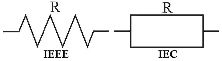
- Zig-zag symbol – ANSI / American standard
- Rectangular symbol – IEC / European standard
In practice, the type of resistor (wire wound, metal film, carbon) is specified in the Bill of Materials (BOM) rather than the circuit symbol.
Related Articles:
- Carbon Composition Resistor Construction, Working & Applications
- Carbon Film Resistor Construction, Working, Types & Applications
- Metal Film Resistor Construction, Working, Types and Applications
- Metal Oxide Resistor Construction, Working, Types & Applications
- Types of Resistors with Symbol, Classification and Applications
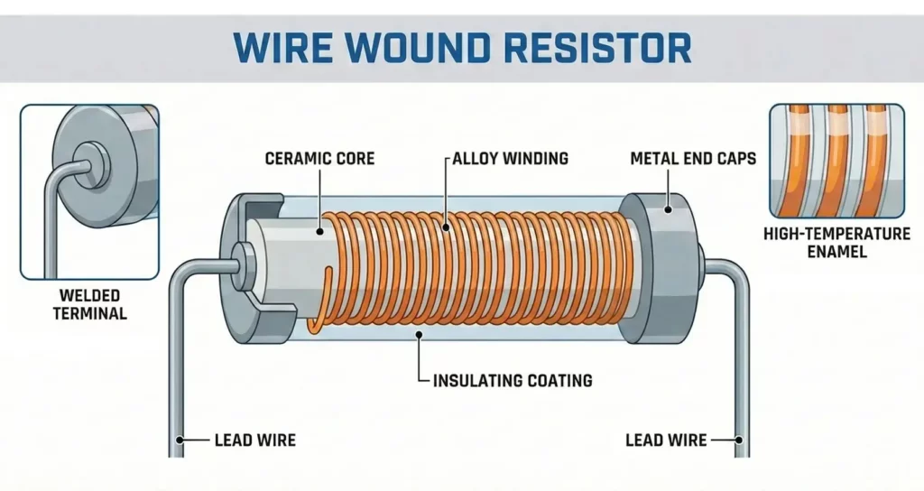
Construction of Wire Wound Resistor
The construction of a wire wound resistor is mechanically robust and thermally optimized, making it suitable for high-power applications. Main construction elements of this resistor are as follow.
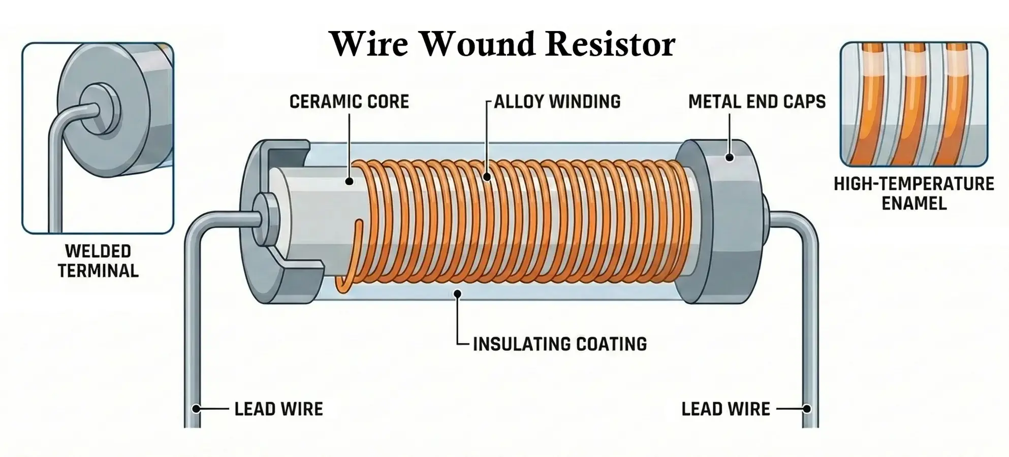
- Resistive Wire
- The resistance is formed using metal alloy wire, commonly: Nichrome (Nickel-Chromium), Manganin, Constantan, Nickel-Copper alloys.
- These materials are chosen for:
- High resistivity
- Low temperature coefficient
- Good oxidation resistance
- Insulating Core
- Usually ceramic, porcelain, or fiberglass
- Provides mechanical strength and electrical insulation
- Withstands high temperatures
- Winding Process
- The resistive wire is uniformly wound around the core
- Can be single-layer, bifilar, or Ayrton-Perry winding
- Special winding techniques reduce inductance
- Protective Coating: Cement coating, Vitreous enamel coating, Silicone or epoxy coating. This layer:
- Protects from moisture
- Improves heat dissipation
- Prevents mechanical damage
- Terminals / Leads
- Axial leads
- Radial leads
- Solder lugs or screw terminals for high-power types
Working Principle of Wire Wound Resistor
The working of a wire wound resistor is based on Ohm’s Law:
V = I × R
- When voltage is applied across the terminals, current flows through the resistive wire.
- Due to the wire’s resistivity, electrical energy is converted into heat energy.
- The ceramic core and outer coating dissipate heat into the surrounding environment.
- The resistor maintains a stable resistance value over a wide temperature range.
Because current flows through a physical wire, wire wound resistors can exhibit inductive behavior, especially at high frequencies.
Electrical and Physical Characteristics
- Resistance Range
- Typically, from 0.01 Ω to 100 kΩ
- Very low resistance values are easily achievable
- Power Rating
- From 1 W to several kilowatts
- Common ratings: 1 W, 5 W, 10 W, 50 W, 100 W
- Tolerance: ±0.01%, ±0.1%, ±1%, ±5%
- Temperature Coefficient (TCR)
- Very low (±5 to ±50 ppm/°C)
- Suitable for precision circuits
- Noise Performance
- Extremely low electrical noise
- Ideal for measurement and instrumentation
- Frequency Response
- Poor at high frequencies due to inductance
- Not suitable for RF applications unless non-inductive types are used
How to Read Value of Wire Wound Resistor
Color Code Method (Low Power Types)
Some small wire wound resistors use standard resistor color codes:
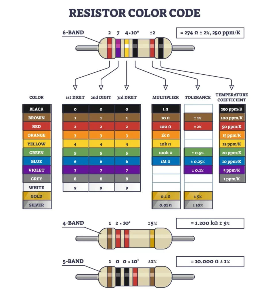
- First two or three bands → Significant digits
- Next band → Multiplier
- Last band → Tolerance
Example: Brown-Black-Red-Gold = 1 kΩ ±5%
Printed Value Method (High Power Types)
High-power wire wound resistors usually have values printed directly:
- Resistance:
10Ω,0.22Ω - Power:
10W,50W - Tolerance:
±5%
Example marking: 10Ω 25W ±5%
Ohmmeter Measurement
- Measure resistance using a digital multimeter
- Ensure resistor is disconnected from the circuit
Types of Wire Wound Resistors
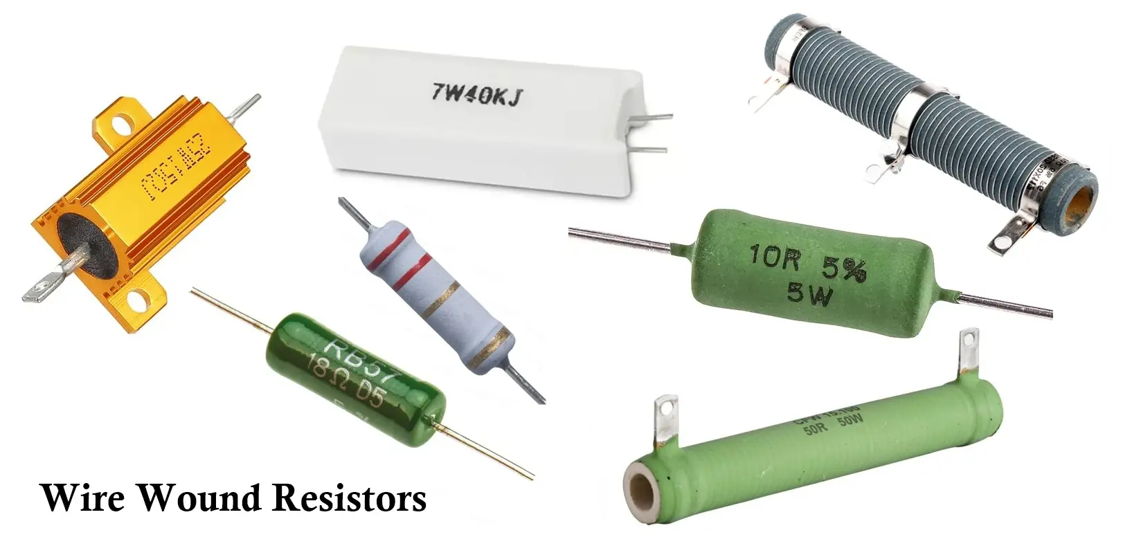
- Cement Wire Wound Resistors
- Cement-coated rectangular body
- Economical and robust
- Common in power supplies
- Vitreous Enamel Wire Wound Resistors
- Glass-like enamel coating
- High temperature resistance
- Used in industrial environments
- Aluminum Housed Wire Wound Resistors
- Metal enclosure for heat sinking
- Designed for chassis mounting
- Used in motor drives and braking circuits
- Non-Inductive Wire Wound Resistors
- Special winding techniques
- Minimal inductance
- Suitable for pulse and AC circuits
- Precision Wire Wound Resistors
- Very tight tolerance
- Low TCR
- Used in calibration and metrology
Selection Criteria for Wire Wound Resistors
When selecting a wire wound resistor, consider:
- Electrical Factors
- Required resistance value
- Power dissipation margin (use ≥ 2× rated power)
- Tolerance and stability
- Temperature coefficient
- Thermal Considerations
- Ambient temperature
- Cooling method (air, heatsink)
- Frequency Considerations
- Avoid inductive types in AC or high-frequency circuits
- Choose non-inductive versions when needed
- Mechanical Factors
- Size and mounting method
- Vibration resistance
- Environmental protection
Advantages of Wire Wound Resistors
- High power handling capability
- Excellent long-term stability
- Very low noise
- High accuracy and precision
- Wide operating temperature range
- Suitable for high current applications
Disadvantages of Wire Wound Resistors
- Inductive behavior limits high-frequency use
- Larger size compared to film resistors
- Higher cost than carbon resistors
- Limited maximum resistance value
- Not suitable for compact, high-density PCBs
Applications of Wire Wound Resistors
Wire wound resistors are widely used in:
- Power supply circuits
- Current sensing and shunt resistors
- Motor speed controllers
- Braking resistors in drives
- Load banks and dummy loads
- Audio amplifiers (power stages)
- Industrial control panels
- Battery charging and discharging systems
- Test and measurement equipment
Comparison with Other Resistors
- Accuracy: Higher precision and tighter tolerance than carbon and thick-film resistors
- Power Handling: Much higher power rating than carbon film, metal film, and thick film
- Stability: Excellent thermal and long-term stability compared to most other types
- Noise: Very low electrical noise (better than carbon composition/film)
- Inductance: Inductive by nature → worse for high-frequency applications than metal/thick film
- Size: Bulkier for the same resistance value than film resistors
- Resistance Range: Limited to low–medium resistance values (not suitable for very high Ω)
- Cost: More expensive than carbon film and thick-film resistors
- Typical Use: Power supplies, current sensing, load resistors (vs. signal paths for metal film)
Summary Table
| Parameter | Wire Wound Resistor |
|---|---|
| Resistive Element | Metal alloy wire |
| Resistance Range | 0.01 Ω to 100 kΩ |
| Power Rating | 1 W to kW range |
| Tolerance | ±0.01% to ±5% |
| Temperature Stability | Excellent |
| Noise Level | Very low |
| Frequency Response | Limited (inductive) |
| Physical Size | Large |
| Cost | Moderate to high |
| Typical Applications | Power & industrial circuits |
Conclusion
Wire wound resistors remain one of the most reliable and rugged resistor types in electronics. While their inductive nature restricts use in high-frequency circuits, their exceptional power handling, precision, and thermal stability make them indispensable in power electronics and industrial systems. Proper selection and thermal management ensure long service life and dependable performance.
Types of Resistors with Symbol, Classification and Applications
Metal Oxide Resistor Construction, Working, Types and Applications
Carbon Composition Resistor Construction, Working & Applications
Carbon Film Resistor Construction, Working, Types and Applications