A varactor diode is a specialized semiconductor device widely used in electronics to utilize its property of variable capacitance. By understanding its symbol, construction, working principles, and applications, engineers can design systems that take advantage of its unique characteristics. This article provides a detailed overview of the varactor diode.
Varactor Diode Symbol
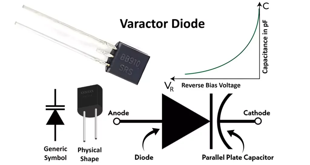
The symbol of a varactor diode consists of a standard diode symbol (triangle pointing to a line) with a capacitor symbol (two parallel lines) placed parallel to the first line. This representation highlights the diode’s ability to act as a variable capacitor. The anode is denoted by the triangle, and the cathode by the vertical line. Gap between two lines represents dielectric.

Construction of Varactor Diode
The structure of a varactor diode is designed to utilize its voltage-dependent variable capacitance. A varactor diode, also called as varicap diode or tuning diode, operates based on the properties of the depletion region in a PN junction. Here’s a breakdown of its structure:
1. Basic PN Junction
- The varactor diode is essentially a PN junction diode.
- When reverse-biased, it creates a depletion region (a region devoid of free charge carriers) at the junction between the p-type and n-type semiconductor materials.
2. Depletion Region
- The width of the depletion region changes depending on the applied reverse voltage:
- Increased reverse voltage → Depletion region widens → Capacitance decreases.
- Decreased reverse voltage → Depletion region narrows → Capacitance increases.
- This dynamic change in the width of the depletion region is what gives the varactor its variable capacitance property.
3. Heavily Doped Regions
- The p-type and n-type regions are typically heavily doped to create a sharp junction. This helps in achieving high precision in capacitance variation with voltage.
- The doping profile might also be tailored to optimize the capacitance range and linearity.

4. Contact Layers
- Metal contacts are provided on both the p-type and n-type regions to allow for electrical connections.
- These contacts are made using materials that provide low resistance for efficient conduction.
5. Encapsulation
- The varactor diode is enclosed in a protective package to shield it from physical damage, contamination, and environmental factors like moisture and dust.
6. Special Structures
In some advanced varactor diodes:
- The junction is fabricated as a hyper abrupt junction, where the doping concentration changes abruptly near the junction, providing better control over the capacitance range.
- A planar design is often used for consistent electrical and thermal characteristics.
Summary of Layers in Varicap Diode:
- Metal Contact (to p and n type region)
- P-type Semiconductor (heavily doped region)
- Depletion Region (changes width with voltage)
- N-type Semiconductor (heavily doped region)

Working of Varactor Diode
The operation of a varactor diode relies on its ability to vary capacitance by changing the reverse bias voltage:
- Reverse Bias: When reverse-biased, the junction between the P and N regions acts as a capacitor.
- Capacitance Variation: As the reverse voltage increases, the depletion region widens, reducing capacitance. Conversely, decreasing the reverse voltage narrows the depletion region, increasing capacitance.
- Frequency Tuning: By integrating a varactor diode into an LC circuit (inductor-capacitor circuit), the capacitance can be adjusted dynamically to tune the circuit’s resonant frequency.
Characteristics of Varactor Diode
The capacitance of a varactor diode is determined by the depletion region formed at the p-n junction when reverse-biased. The characteristics of a varactor diode describe its behavior under varying voltage conditions. The key characteristics are as follows:

- Depletion Region Width:
When a reverse voltage is applied, the electric field widens the depletion region. A wider depletion region corresponds to lower capacitance because capacitance is inversely proportional to the separation distance between the charges (the width of the depletion layer). - Capacitance Formula:
The capacitance C of the varactor diode is given by:C = εA/dwhere:
ϵ: Permittivity of the material
A: Junction area
d: Depletion region width (increases with reverse voltage) - Capacitance and Reverse Bias Voltage:
The capacitance is inversely proportional to the reverse voltage. The relationship between capacitance and reverse voltage ( Vr ) is nonlinear and given by:
Cj = C * K / (Vb - Vr)-mWhere:
- Cj: Capacitance of the diode at a given reverse voltage.
- C: Capacitance of the diode when the device is unbiased.
- Vr: Reverse bias voltage applied across the diode.
- Vb: Barrier voltage of the junction (depends on the material).
- m: Constant depending on the material:
- Abrupt junction:
m = 1/2 - Graded junction:
m = 1/3
- Abrupt junction:
- K: Constant equal to 1.
This shows that as the reverse voltage increases, the capacitance decreases nonlinearly.
- Quality Factor of the Varactor Diode
Q = F / fWhere:
- Q: Quality factor of the varactor diode.
- F: Maximum operating frequency of the diode.
- f: Operating frequency of the circuit.
- Maximum Operating Frequency
F = 1 / (2π * Rs * Cj)Where:
- F: Maximum operating frequency of the varactor diode.
- Rs: Series resistance of the varactor diode.
- Cj: Capacitance of the diode at a given reverse bias voltage.
Voltage Range
- Varactor diodes are designed to operate in the reverse-biased mode to prevent forward conduction.
- The typical operating range of reverse voltage depends on the diode design but is often in the range of 1V to 30V.
Capacitance Range
- The capacitance range of a varactor diode depends on its construction but typically varies from a few picofarads (pF) at high reverse voltages to hundreds of picofarads at low reverse voltages.
Nonlinearity
- The nonlinearity in the capacitance-voltage relationship can affect tuning precision in RF circuits.
- To mitigate this, linearization techniques or diodes with specific doping profiles are used to achieve a smoother capacitance variation.

Advantages of Varactor Diode
- Variable Capacitance:
The capacitance of a varactor diode can be easily controlled by changing the reverse bias voltage, making it highly suitable for tuning applications. - Compact and Lightweight:
Varactor diodes are small and lightweight, making them ideal for compact electronic devices like radios, televisions, and mobile phones. - Low Power Consumption:
Since varactor diodes operate with reverse bias, they consume very little current, making them energy-efficient. - High Frequency Performance:
They can operate effectively at high frequencies, which is essential for RF applications such as frequency modulation (FM) and phase-locked loops (PLLs). - Wide Capacitance Range:
Varactor diodes offer a wide range of capacitance, which provides greater flexibility in tuning applications. - Reliability:
Due to their simple structure and lack of moving parts, varactor diodes are reliable and durable. - Cost-Effective:
They are relatively inexpensive compared to mechanical tuning systems or other electronic tuning components. - Integration with Circuits:
Varactor diodes can easily be integrated into ICs or other circuits, making them ideal for miniaturized systems.
Disadvantages of Varactor Diode
- Nonlinear Capacitance:
The capacitance of a varactor diode is nonlinear and depends on the reverse bias voltage. This nonlinearity can introduce distortion in certain applications, such as AM modulation. - Limited Power Handling:
Varactor diodes are not suitable for high-power applications due to their limited current-handling capability and thermal constraints. - Reverse Voltage Limitations:
Exceeding the reverse voltage rating can damage the varactor diode, limiting its usage in circuits with high voltage variations. - Temperature Sensitivity:
The performance of a varactor diode is sensitive to temperature changes, which can affect the capacitance and stability of the circuit. - Low Quality Factor (Q-factor):
The quality factor of varactor diodes is lower compared to other tuning components like quartz crystals, which may lead to signal losses in high-frequency applications. - Narrow Applications:
Varactor diodes are mainly used in tuning and frequency modulation applications, which limits their utility in broader circuit designs. - Capacitance Range Limitations:
Although they offer a variable range of capacitance, it is still limited compared to other capacitor types, which can restrict certain design requirements. - Parasitic Effects:
At very high frequencies, parasitic inductance and resistance may degrade the performance of the varactor diode.
Applications of Varactor Diode
1. Voltage-Controlled Oscillators (VCOs)
Varactor diodes are widely used in oscillators for frequency tuning. By varying the reverse voltage, the capacitance of the varactor diode changes, altering the resonant frequency of the LC circuit. Major applications include – frequency modulation (FM) radios, phase-locked loops (PLLs) and signal synthesizers.
2. Frequency Modulation (FM) and Phase Modulation (PM)
Modulators use varactors to vary the frequency or phase of a carrier signal in proportion to an input signal, enabling FM or PM transmission.
3. Automatic Frequency Control (AFC) Circuits
Varactor diodes stabilize the frequency of oscillators in radios, television receivers, and communication systems in AFC circuits.
4. Tunable Filters
Tunable bandpass and low-pass filters rely on varactor diodes. Their capacitance dynamically adjusts to select or filter specific frequency bands. Major applications include RF tuning, radar systems, and spectrum analyzers.
5. Voltage-Controlled Capacitors
In RF circuits, varactors fine-tune impedance matching networks by functioning as voltage-controlled capacitors.
6. Phase-Locked Loops (PLLs)
Varactors dynamically adjust frequencies in PLLs to synchronize communication systems.
7. Parametric Amplifiers
In microwave and RF systems, parametric amplifiers use varactors to amplify weak signals based on their nonlinear capacitance properties.
8. TV Tuners
Older analog TV sets used varactor diodes for channel selection and tuning by varying the reverse bias voltage.
9. Antenna Tuning
Antenna systems utilize varactors to dynamically adjust the resonant frequency, improving efficiency and bandwidth.
10. Frequency Multipliers
Frequency multiplier circuits use varactor diodes, where their nonlinear capacitance generates harmonics of an input signal.
11. Satellite Communication
Satellite communication systems rely on varactors for precise tuning of oscillators and filters.
12. Microwave Applications
Microwave systems integrate varactors into devices such as phase shifters, voltage-controlled phase delays, and RF tuning circuits.
Conclusion
The varactor diode is a vital component in modern electronics, especially in RF and communication systems, due to its unique variable capacitance property. While it has some limitations, its advantages far outweigh them in applications requiring precise frequency control and tuning. Understanding its symbol, construction, characteristics, and working principles helps engineers design efficient and reliable systems.
Types of Diodes with Symbol, Definition, Working and Applications