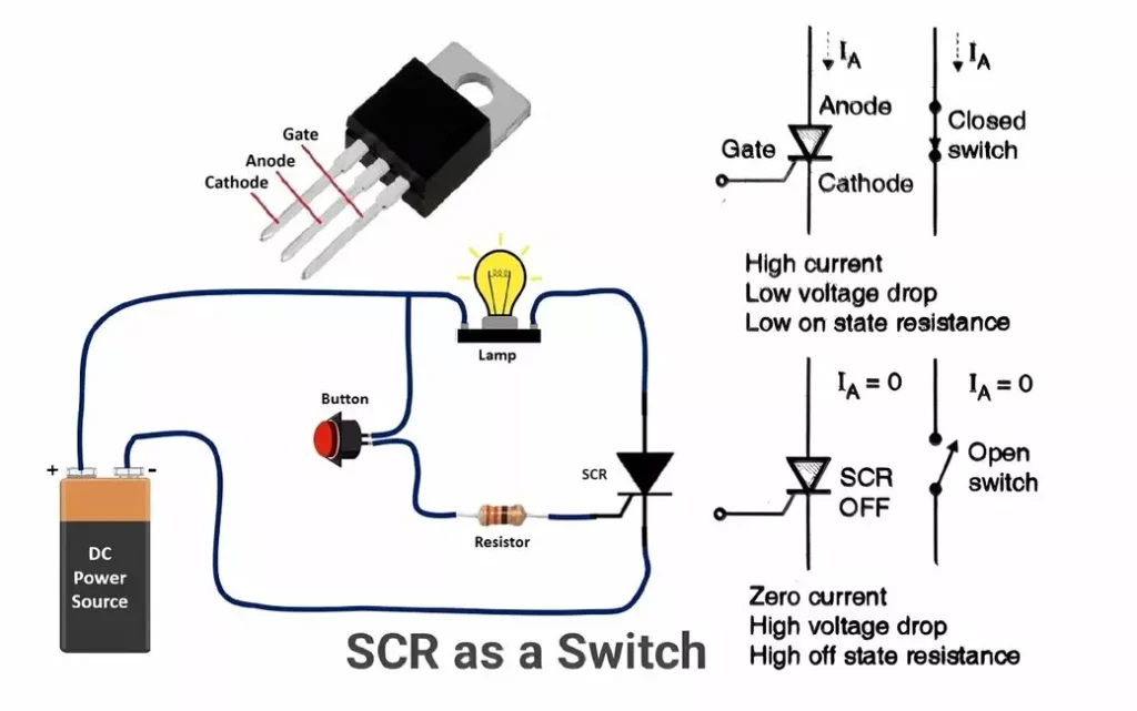
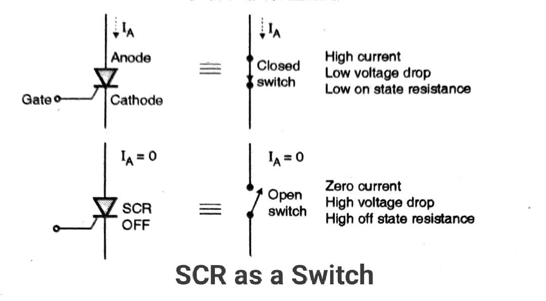
The SCR has only two states of operation i.e. it can be either fully ON or completely OFF hence SCR can as a switch. There is no “active” region of operation like a transistor. Therefore, SCR as a switch is used in a huge variety of electronic circuits due to its great features.
As it cannot operate in the active region, it cannot be used as an amplifier.
Please do read these articles to understand the concept, working of silicon controlled rectifier, and VI characteristics of(SCR) silicon controlled rectifier.
Rate Effect in PNPN Diode:
The rate effect is applicable to the SCR as well. The forward breakover voltage of a p-n-p-n switch depends on the “rate” at which the applied voltage rises. shows the equivalent circuit of the p-n-p-n diode in its off state.
It is a series combination of three diodes. D1 and D3 represent the forward-biased junctions J1 and J3 whereas D2 represents the reverse-biased junction J2.
Capacitor C represents the transition of the reverse-biased junction.
When the applied voltage V rises rapidly, the capacitor voltage rises at the rate of dV/dt. Due to this a current C dV/dt passes through C and adds to the current through D1 and D3.
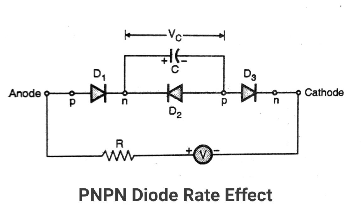
Therefore, the breakdown of D2 will take place at a lower voltage. Thus, due to the high rate of increase of applied voltage, the breakover voltage of the p-n-p-n diode will reduce.
That means with the gate terminal open, i.e. Ig = 0, the SCR can be turned on if the rate of rise of externally applied anode-to-cathode voltage is high enough.
This is called as the accidental turn-on of an SCR. It is an undesired characteristic and should be avoided. In order to avoid the accidental turn-on of an SCR, a circuit called “snubber” is connected across it as shown.
RC snubber circuit:
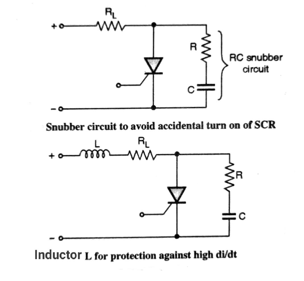
The RC snubber circuit of as shown in the figure reduces the rate of rise of voltage across the SCR and avoids the accidental turn on.
An SCR is protected from damage due to a high rate of change of current by connecting an inductance in series with it as shown in. This inductance reduces the rate of increase of SCR current at the time of turn-on.
Methods to turn ON SCR switch:
A thyristor is turned on by increasing the anode current. This I can be achieved with one of the following ways,
- By raising the temperature (Thermal triggering).
- By focusing light (Optical triggering).
- Applying a high voltage (Forward voltage triggering).
- By applying a voltage at high dv/dt (dv/dt triggering).
- By increasing the gate current (Gate triggering).
Methods to turn OFF SCR:
The SCR can be turned on by gate current but once turned on, the gate loses control. Even if we reduce the gate current to zero, SCR continues to conduct. We can turn off a conducting SCR by:
- Reducing its anode current below the holding current for a minimum specified time.
- Applying a reverse voltage across the SCR
Important Features of SCR as a switch:
- It is a latching type of device.
- It can handle a very large power.
- SCR is a current-controlled device because the gate current controls SCR.
- It acts as an open or closed switch, but it cannot be used as an amplifier.
- The on-state voltage drop is very low.
- It can handle thousands of amperes of current.
Typical Ratings of SCR:
| SR, NO | Description | VALUE |
|---|---|---|
| 1 | On-state voltage Vt | 1.5 to 2.5 Volts |
| 2 | Turn off time t | 50 to 100 uS |
| 3 | The maximum rate of change of voltage dV/dt | 1000 V/uS |
| 4 | The maximum rate of change of current di/dt | 500 A/uS |
| 5 | Maximum switching frequency | 400 Hz |
Drawbacks of SCR:
- It can conduct only in one direction. So, it can control power only during one-half cycle of ac.
- It can turn on accidentally due to the high dv/dt of the source voltage.
- It is not easy to turn off the conducting SCR. We have to use special circuits called commutation circuits to turn off a conducting SCR.
- SCR can not be used at high frequencies. The maximum frequency of its operation is 400 Hz.
- Gate current can’t be negative.
Advantages of SCR:
- It can handle large voltages, currents, and power.
- The voltage drop across conducting SCR is small. This will reduce the power dissipation in the SCR.
- Easy to turn on.
- Triggering circuits are simple.
- It can be protected with the help of a fuse.
- We can control the power delivered to the load.
Applications of SCR as a switch:
- Controlled rectifiers
- DC to DC converters or choppers.
- DC to AC converters or inverters.
- As a static switch.
- Battery chargers
- Speed control of DC and AC motors
- Lamp dimmers, Fan speed regulator
- AC voltage stabilizers