The circuit in which output voltage waveform is an integration of the input signal is called as an integrator or op-amp integrator or integrating amplifier. The output voltage is proportional to the amplitude and duration of the input signal.
Ideal op amp Integrator Circuit:
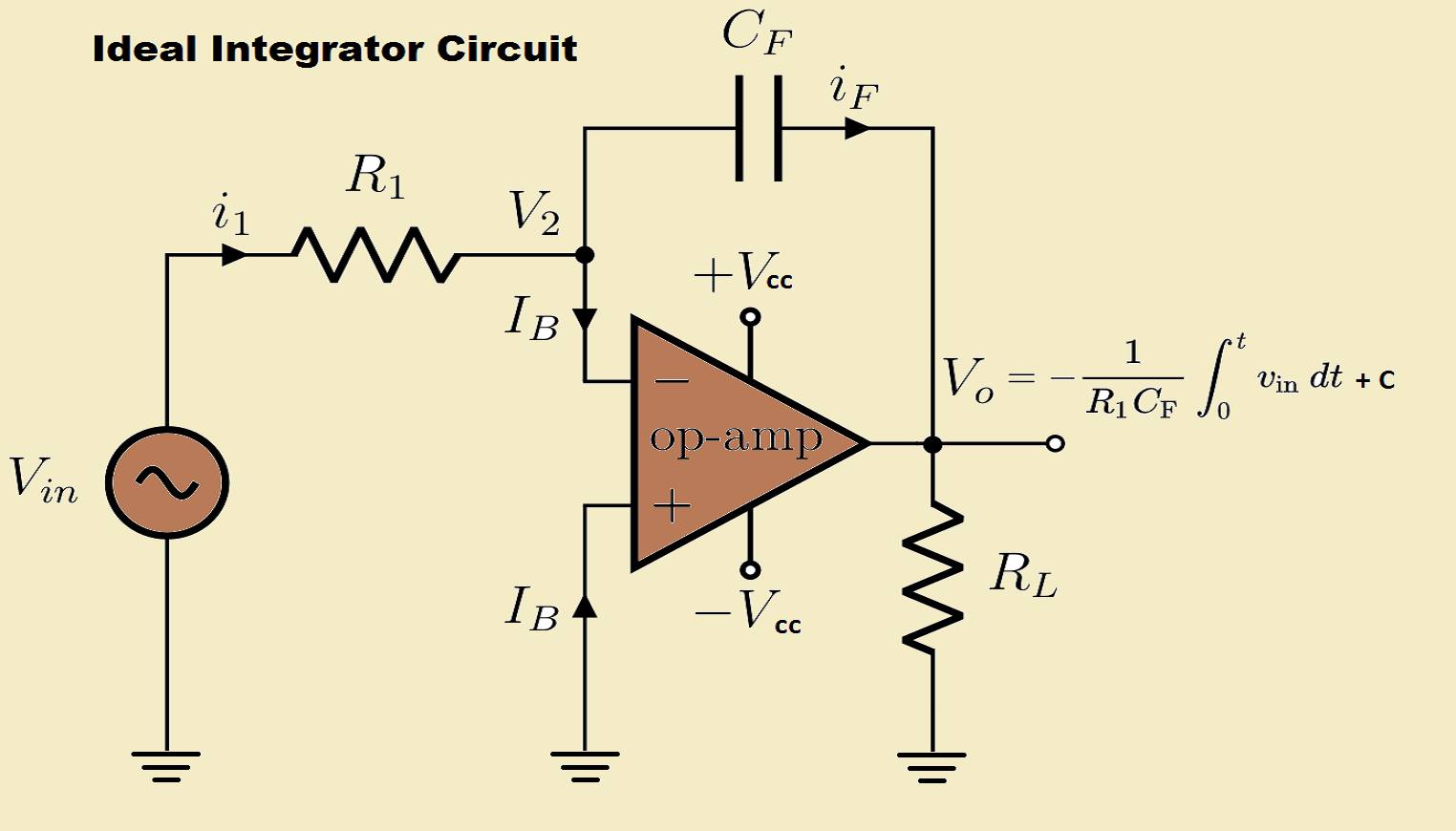
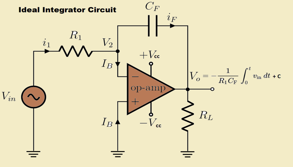
The above circuit is obtained by replacing the feedback resistor RF in the inverting amplifier configuration by a capacitor Cf. We assume that opamp used here is an ideal one. V2 is at virtual ground potential. R1 is the input resistance and RL is load resistor.
Expression for the output voltage:
- Applying Kirchhoff’s current law at node V2, we get
I1 = IB + IF
- As the input impedance, Ri is very high, IB is negligible hence,
I1 = IF
- The relation between current and voltage across the capacitor Cf is given by
I1 = Cf×(dVc/dt)
But,
I1 = Vin - V2÷R1 and Vc = (V2 - V0)
- Substituting the value of I1 in the above equation,
(Vin - V2)÷R1 = Cf × d/dt×(V2 - V0)
- By using the concept of “virtual ground” we can write that V2 = 0
- Substituting V2 in the above equation we get,
Vin÷R1 = Cf × d/dt×( -V0 )
- The output voltage can be found by integrating the above equation.
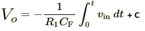
- where C is the constant of integration, it is proportional to the output voltage at t = 0 seconds.
- From the above equation, we can say that the output is [-1/(R1 * Cf)] times the integral of the input voltage. R1 and Cf are time constants.
- The negative sign indicates that there is a phase shift of 180 degrees between input and output signals, as the input is provided at the inverting input of the op-amp.
Practical OP-AMP integrator circuit:
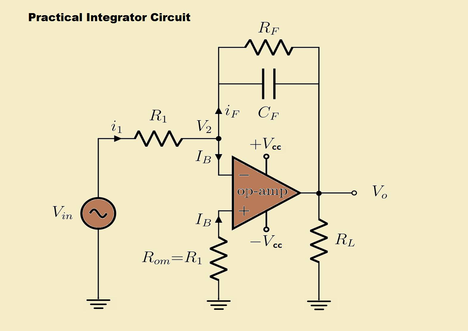
A practical opamp circuit is different from an ideal opamp. There is a feedback resistor Rf present in parallel with the feedback capacitor. The value of Rf is very high.
Practical op-amps are having finite open-loop gain, input offset voltage, and input bias currents. Due to this, there may be an output voltage without any input signal. The large value Rf resistor is used to reduce this effect.
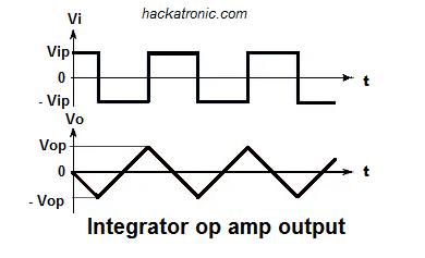
Opamp Integrator as Ramp signal Generator
When a square wave is applied at the input terminal of the integrator, due to change in the input signal amplitude the feedback capacitor keeps charging and discharging.
During both positive and negative half-cycles, the current flows through the input resistor R1, and through the capacitor Cf, the current flowing through the input terminal of the op-amp is zero.
The capacitor is connected to virtual ground the voltage across the capacitor is the output voltage of op-amp.
When the negative half cycle arises the direction of current is reversed and the capacitor linearly charges to produces a positive-going ramp output.
The output of the circuit is a triangular wave whose frequency is dependent on the value of R1 and Cf. This circuit is commonly known as a ramp generator circuit.
Output for a sinewave input signal:
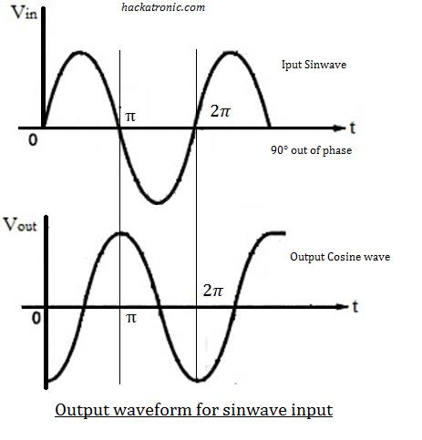
When AC input is applied at the inverting input terminal the output voltage produced is 90° out of phase with the input signal, producing a cosine wave.
When the input signal is a triangular wave, the output waveform is sinusoidal. The above circuit acts as an active low pass filter.
Advantages of op amp integrator:
- Low distortion.
- Better linearity.
- Gain can be controlled.
- Sharp frequency response.
- Less effect of noise.
- The circuit is highly stable with less possibility of oscillations
Disadvantages of op-amp integrator:
- It can operate as an integrator over a shot frequency range.
- Beyond this frequency range output gets distorted.
- Op amp parameters affect the output waveform and voltage.
- Gain reduces with an increase in frequency.
- Errors may get introduced due to bias current, input bias voltage.
Applications of an OP AMP integrator:
Here are some important applications of integrator as follow:
- In the triangular wave or ramp generators.
- Used in Analogue to digital ( A to D ) converters.
- In the integral type controller used in a closed-loop control system.
- In analog computers to solve differential equations.
- As an active low pass filter.
- In the communication circuits for recovering the modulating signal.
OP-AMP tutorial:
-
Opamp as Differentiator (active differentiator)
-
OP AMP integrator
-
Voltage Follower OPAMP or buffer Amplifier
-
Non Inverting Amplifier (OPAMPs)
-
Inverting amplifier (OPAMPs)
-
741 Op Amp, First Operational Amplifier IC
-
What is operational amplifier? basics concepts
-
Automatic Battery Charger circuit using LM358 OP-AMP