A metal film resistor is a precision fixed resistor widely used in electronic circuits where high accuracy, stability, and low noise are required. Compared to carbon composition and carbon film resistors, metal film resistors offer tighter tolerance, lower temperature coefficient, and superior long-term reliability.
They are extensively used in analog circuits, instrumentation, audio equipment, medical electronics, industrial control systems, and precision measurement devices, where signal integrity is critical.
Metal Film Resistor Symbol
The schematic symbol of a metal film resistor is the same as that of any fixed resistor:
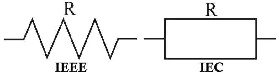
- Zig-zag line (ANSI standard – commonly used in the USA)
- Rectangular box (IEC/European standard)
Since metal film resistors are fixed resistors, no special symbol differentiation is required in circuit diagrams. The type is usually identified in bill of materials (BOM), circuit description and component specification notes.
Related Articles:
- Carbon Composition Resistor Construction, Working & Applications
- Carbon Film Resistor Construction, Working, Types & Applications
- Types of Resistors with Symbol, Classification and Applications
Construction of Metal Film Resistor
1. Core Structure
The core of a metal film resistor consists of a high-purity ceramic rod (usually alumina). This ceramic substrate provides:
- Mechanical strength
- Electrical insulation
- Thermal stability
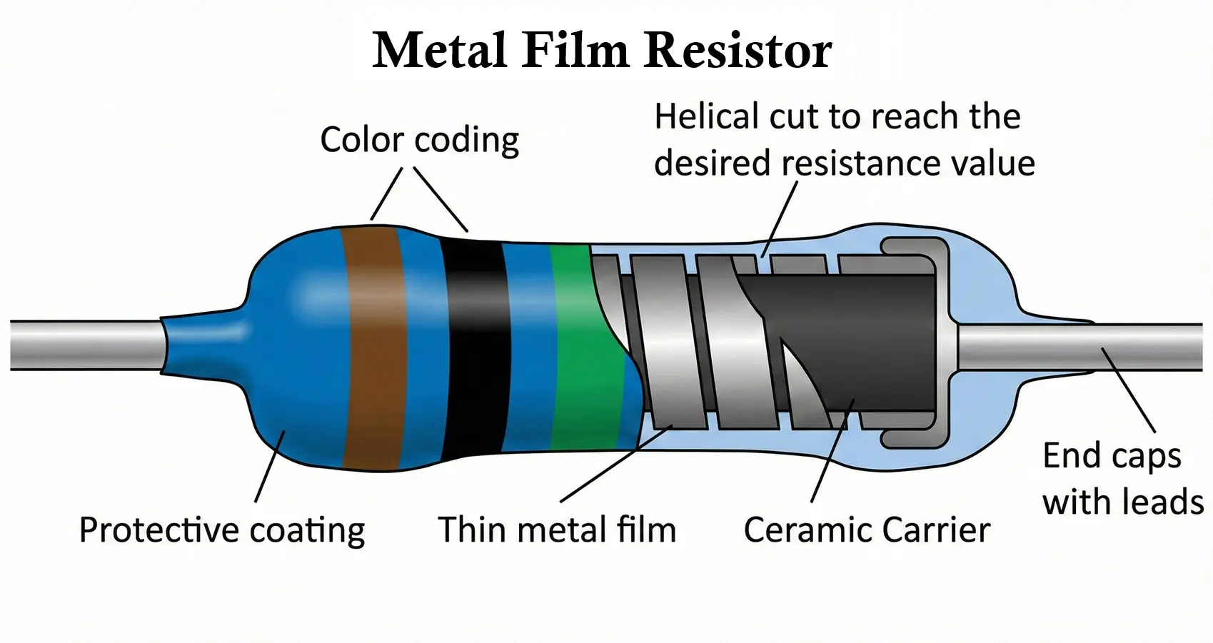
2. Metal Film Deposition
A thin layer of metal or metal alloy is deposited uniformly on the ceramic rod using vacuum deposition or sputtering techniques. Common materials include:
- Nickel-chromium (NiCr)
- Tin oxide-based alloys
- Chromium-based alloys
The thickness of the metal film directly influences the resistance value.
3. Spiral Cutting (Trimming)
To obtain precise resistance values, the metal layer is laser- or machine-cut into a helical spiral. This increases the effective length of the resistive path and allows:
- Fine resistance adjustment
- High accuracy (down to ±0.1% tolerance)
4. End Caps and Leads
Metal end caps are attached to both ends of the ceramic rod, and tinned copper leads are welded to these caps, providing:
- Good electrical conductivity
- Easy PCB mounting
5. Protective Coating
The resistor is coated with epoxy resin or lacquer, which:
- Protects against moisture and oxidation
- Provides electrical insulation
- Improves mechanical durability
Working Principle of Metal Film Resistor
The operation of a metal film resistor is based on Ohm’s Law:
V = IR
When a voltage is applied across the resistor terminals:
- Electrons flow through the thin metal film
- The metal film offers resistance due to atomic collisions
- A small electrical energy is converted into heat
Because the resistive element is metallic and uniform:
- Noise generation is minimal
- Resistance remains stable over time and temperature
Electrical Characteristics of Metal Film Resistors
- Resistance Range
- Typically, from 1 Ω to 10 MΩ
- Some precision versions extend beyond this range
- Tolerance
- Common tolerance values include: ±5%, ±2%, ±1%, ±0.5%, ±0.1% (precision-grade resistors)
- Temperature Coefficient (TCR)
- Very low TCR: ±5 ppm/°C to ±100 ppm/°C
- Ensures minimal resistance change with temperature
- Noise Performance
- Extremely low excess noise
- Ideal for low-signal and audio-frequency applications
- Power Rating
- Typical power ratings include: 1/8 W, 1/4 W, 1/2 W, 1 W, 2 W and above (special designs)
- Voltage Rating
- Limited by physical size and insulation
- Typically ranges from 200 V to 500 V
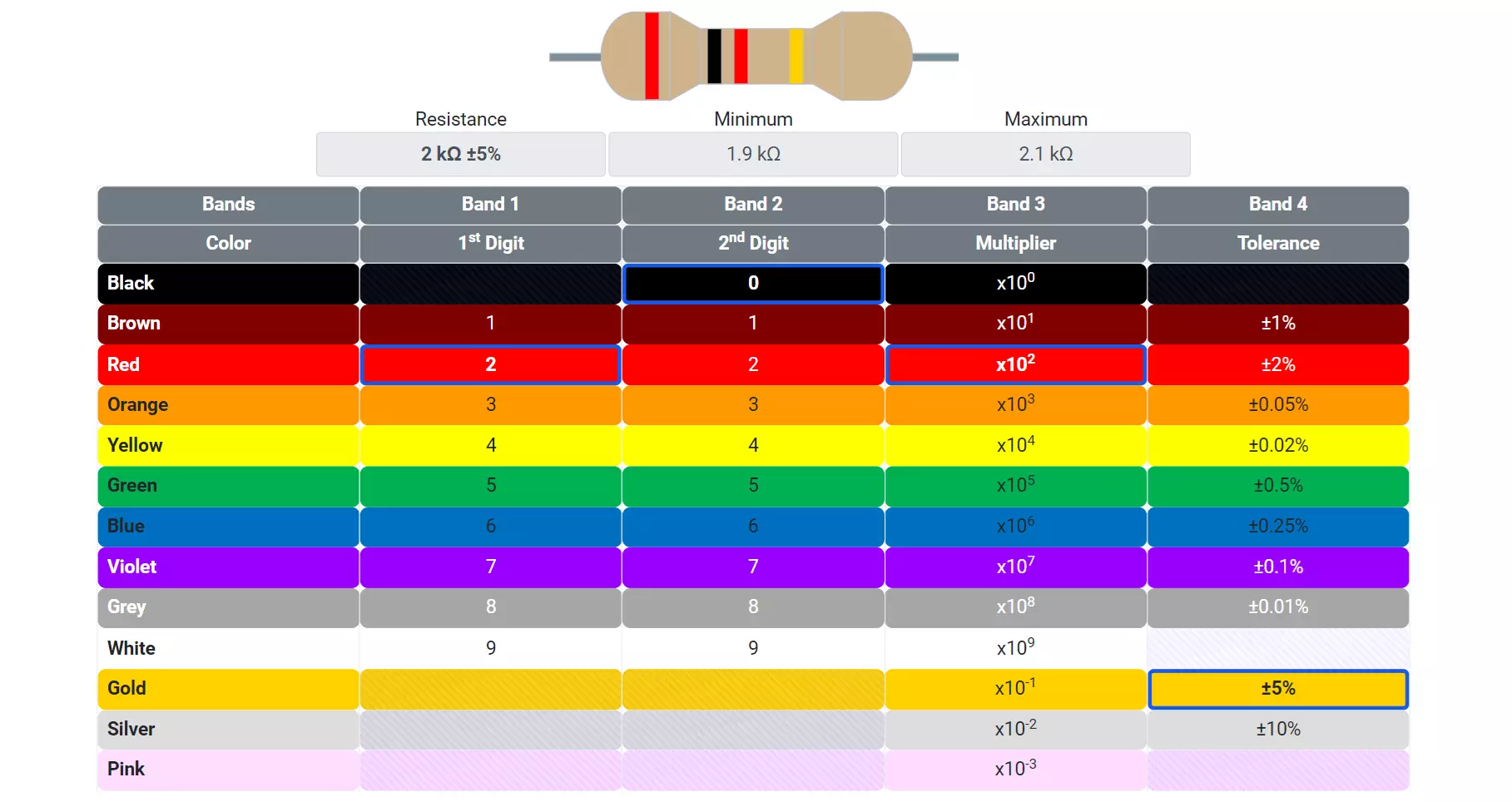
How to Read Metal Film Resistor Value
Metal film resistors use color bands to indicate resistance value, tolerance, and (in some cases) temperature coefficient. They are widely used because of their high accuracy, low noise, and good stability. Metal film resistors commonly use 5-band or 6-band color coding. You can use this resistor color code calculator to find resistor value.
Five-Band Color Code (Metal Film Resistor)
| Band | Meaning | Example (Brown-Black-Black-Red-Brown) |
|---|---|---|
| 1 | First digit | Brown = 1 |
| 2 | Second digit | Black = 0 |
| 3 | Third digit | Black = 0 |
| 4 | Multiplier (×10ⁿ) | Red = ×100 |
| 5 | Tolerance (%) | Brown = ±1% |
Resistance = (100 × 100) = 10,000 Ω or 10 kΩ ±1%
Six-Band Color Code (Metal Film Resistor)
| Band | Meaning | Example (Brown-Black-Black-Red-Brown-Red) |
|---|---|---|
| 1 | First digit | Brown = 1 |
| 2 | Second digit | Black = 0 |
| 3 | Third digit | Black = 0 |
| 4 | Multiplier (×10ⁿ) | Red = ×100 |
| 5 | Tolerance (%) | Brown = ±1% |
| 6 | Temperature Coefficient (ppm/°C) | Red = 50 ppm/°C |
Resistance = (100 × 100) = 10,000 Ω or 10 kΩ ±1%
Temperature coefficient shows resistance change with temperature.
- 5-band → value + tolerance
- 6-band → value + tolerance + temperature coefficient
- Metal film resistors are usually blue and high precision
Printed Value (SMD Type)
Surface-mount metal film resistors use:
- 3-digit or 4-digit numerical codes
- EIA-96 codes for precision resistors
Types of Metal Film Resistors
- Axial Lead Metal Film Resistors
- Through-hole mounting
- Most commonly used type
- Suitable for general-purpose and precision circuits
- Surface Mount (SMD) Metal Film Resistors
- Compact size
- Excellent for high-density PCBs
- Used in modern electronics and automation systems
- Precision Metal Film Resistors
- Ultra-low tolerance (±0.1% or better)
- Very low TCR
- Used in calibration and reference circuits
- High-Voltage Metal Film Resistors
- Designed with longer bodies
- Used in power supplies and high-voltage measurement circuits
Selection Criteria for Metal Film Resistors
When selecting a metal film resistor, consider the following parameters:
- Resistance Value
- Choose standard E-series values (E24, E96, E192)
- Tolerance Requirement
- Precision circuits require ±1% or better
- General circuits may tolerate ±5%
- Temperature Stability
- Low TCR is essential for temperature-sensitive applications
- Power Dissipation
- Always select a resistor with at least 2× safety margin above calculated power
- Noise Sensitivity
- Prefer metal film resistors in low-noise and audio circuits
- Environmental Conditions
- Consider humidity, vibration, and thermal cycling
Advantages of Metal Film Resistors
- High accuracy and tight tolerance
- Excellent temperature stability
- Very low electrical noise
- Long operational life
- Better frequency response
- Consistent performance over time
Disadvantages of Metal Film Resistors
- More expensive than carbon resistors
- Limited surge current handling
- Not suitable for very high pulse energy applications
- Slight inductance due to spiral cut (not ideal for RF at very high frequencies)
Applications of Metal Film Resistors
Metal film resistors are widely used in:
- Precision amplifiers and op-amp circuits
- Audio equipment and signal processing
- Medical and laboratory instruments
- Industrial control and automation systems
- Measurement and calibration equipment
- Power supplies and feedback networks
- Consumer electronics requiring stable performance
Comparison with Other Resistor Types
- Compared to Carbon Composition Resistor: Much more stable and reliable
- Compared to Wire-wound Resistor: Smaller size, better for signal-level circuits
- Compared to Carbon Film Resistor: Better accuracy, lower noise, higher stability
Summary Table
| Parameter | Metal Film Resistor |
|---|---|
| Resistive Material | Nickel-chromium / metal alloy |
| Resistance Range | 1 Ω to 10 MΩ |
| Tolerance | ±5% to ±0.1% |
| Temperature Coefficient | 5–100 ppm/°C |
| Noise Level | Very low |
| Power Rating | 1/8 W to several watts |
| Stability | Excellent |
| Cost | Moderate |
| Typical Applications | Precision, audio, instrumentation |
Conclusion
Metal film resistors represent an ideal balance between precision, reliability, and cost, making them a preferred choice in modern electronic designs. Their low noise, excellent thermal stability, and tight tolerance make them indispensable in analog, measurement, and signal-conditioning circuits. When accuracy and consistency matter, metal film resistors remain one of the most trusted passive components in electronics engineering.
Types of Resistors with Symbol, Classification and Applications
Carbon Film Resistor Construction, Working, Types and Applications
Carbon Composition Resistor Construction, Working & Applications
Types of Capacitors with Symbol, Classification and Applications