Let’s explore the BCD Adder Circuit and learn how it adds decimal digits using Binary Coded Decimal (BCD), a digital coding system in which each decimal digit is represented using a 4-bit binary number. BCD arithmetic is widely used in digital systems where calculations must remain in decimal form, such as calculators, clocks, and display-based instruments.
When two decimal digits represented in BCD format are added together, the resulting binary sum does not always lie within the valid BCD range. To overcome this limitation, a specialized circuit called a BCD Adder is used. This circuit not only performs addition but also applies automatic correction whenever the result becomes invalid in BCD representation.
What is a BCD Adder?
A BCD Adder is a combinational logic circuit designed to add two BCD numbers and produce a valid BCD output.
In BCD representation:
- Each decimal digit uses 4 bits
- The most significant bit is always 0
- Valid BCD values range only from 0000 to 1001
Whenever the sum of two BCD digits exceeds 9, the binary result becomes invalid. A BCD adder detects this condition and adds a correction value of 0110 (decimal 6) to restore the result to a valid BCD form.
Internal Structure of a BCD Adder
A BCD adder is consists of multiple functional blocks working together to ensure correct decimal addition.
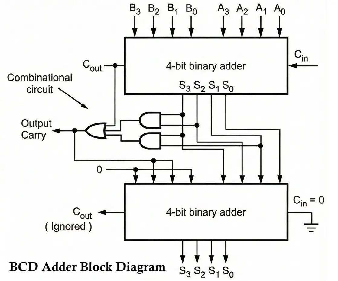
1. 4-bit Binary Adder (Initial Adder)
- Accepts two 4-bit BCD inputs (A3–A0 and B3–B0) and an optional carry-in.
- Produces:
- A 4-bit intermediate sum (S3–S0)
- A carry-out (Cout)
- At this stage, the sum may not be a valid BCD digit.
2. BCD Validity Detection Logic
- This logic checks whether the intermediate sum is valid BCD (0000 to 1001).
3. Correction Logic (Add-6 Circuit)
- When an invalid BCD result is detected, 0110 (decimal 6) is added to the intermediate sum.
- This is done using another 4-bit binary adder.
4. Final BCD Sum Output
- The output of the correction adder provides:
- A valid 4-bit BCD digit
- A decimal carry-out, which is passed to the next higher BCD stage in multi-digit addition.
5. Carry Propagation
- The carry generated after correction represents a decimal carry.
- Used to cascade multiple BCD adders for multi-digit decimal numbers.
- A typical BCD adder consists of:
- Four full adders connected in cascade
- A correction logic circuit
- An additional 4-bit adder to add the correction value
- Each full adder:
- Adds corresponding bits of the two BCD digits
- Accepts a carry-in from the previous stage
- Produces a sum bit and carry-out
- You can implement this circuit using IC7483
Understanding the Range of BCD Addition
A single BCD digit can represent decimal values from:
- 0 → 0000 (binary)
- 9 → 1001 (binary)
When adding two 4-bit BCD digits A and B:
- Minimum sum = 0 + 0 = 0
- Maximum sum (without carry-in) = 9 + 9 = 18
- Maximum sum (with carry-in) = 9 + 9 + 1 = 19
A simple binary adder can produce these values correctly in binary, but the output may not always be valid BCD, which is why correction logic is essential.
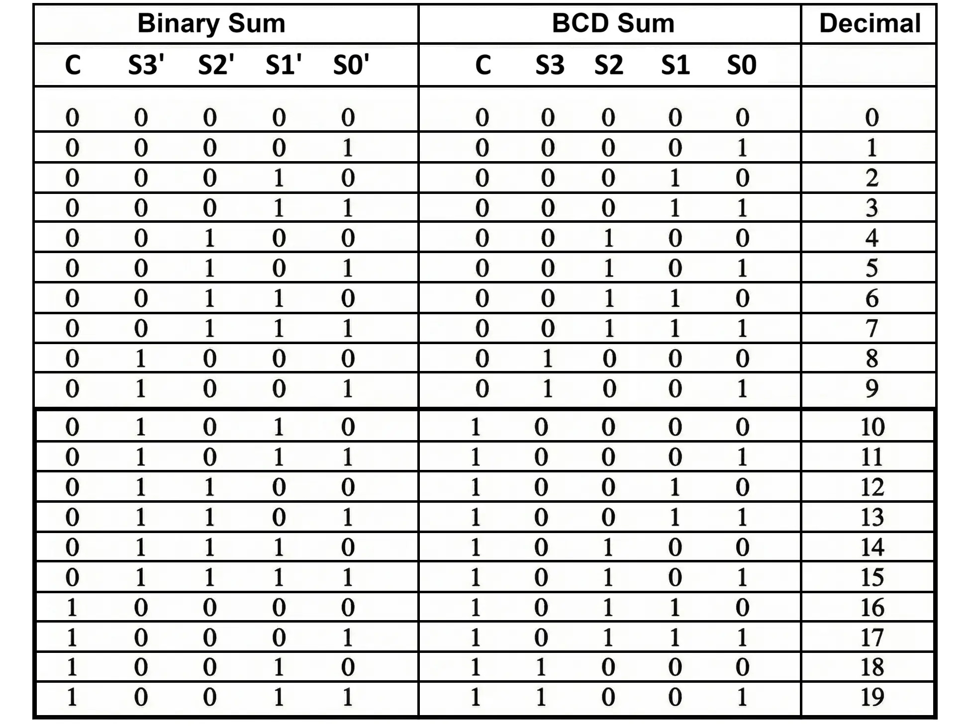
Why is BCD Correction Required?
When adding two BCD digits:
- If the binary sum is ≤ 1001 (9) → result is already valid
- If the binary sum is > 1001 (9) → result is invalid in BCD
To fix this, 0110 (6) is added to the binary sum.
Important Rule
BCD Sum = Binary Sum (if ≤ 9)
BCD Sum = Binary Sum + 0110 (if > 9)
Conditions for Adding 0110 (Correction Logic)
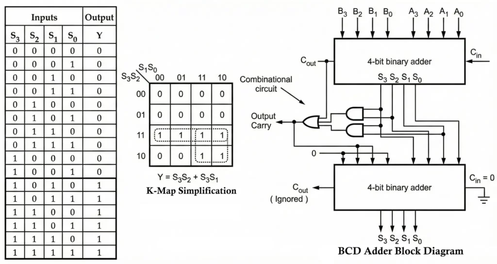
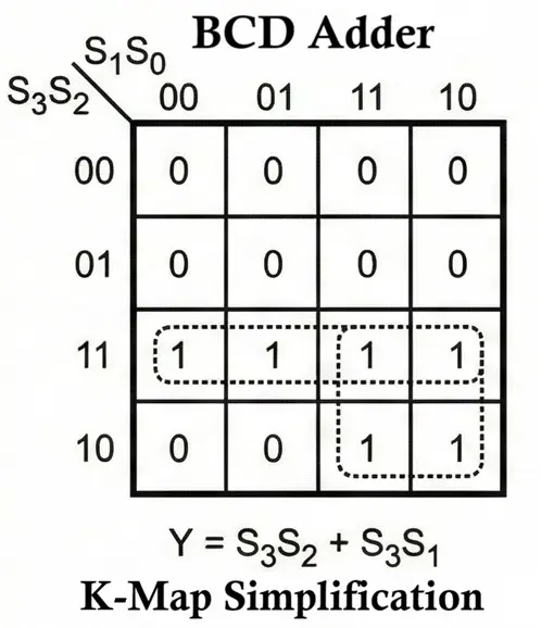
In a BCD adder, the K-map is used to generate the correction logic, which decides when 6 (0110) must be added to the binary sum.
The correction value 0110 is added when any of the following conditions is true:
- Carry output (C′) = 1
(Occurs for decimal sums 16–19) - S3′ · S2′ = 1
(Occurs for decimal sums 12–15) - S3′ · S1′ = 1
(Occurs for decimal sums 10–11)
Final Correction Logic Expression:
Correction = C' + (S3'· S2') + (S3'· S1')
If this expression evaluates to 1, the circuit adds 0110 to the binary sum.
Steps to Design a BCD Adder
- Determine Number of Digits
Each BCD digit requires 4 bits. The number of digits decides how many adder stages are needed. - Select Adder Structure
Use full adders connected in series, with each stage handling one BCD digit and carry propagation. - Implement Full-Adder Circuit
Each full adder must:- Add two BCD bits
- Accept carry-in
- Produce sum and carry-out
- Interconnect Full Adders
Carry-out of one stage is connected to carry-in of the next higher digit. - Provide BCD Correction Logic
Logic gates detect invalid BCD results and enable the addition of 0110. - Test the Circuit
Apply multiple BCD input combinations to verify:- Correct addition
- Proper correction
- Accurate carry handling
Examples
- Example 1
- Input:
- A = 0111 (7)
- B = 1000 (8)
- Binary Sum:
- 0111 + 1000 = 1111 (15)
- BCD Correction Required
- 1111 + 0110 = 1 0101
- Output (BCD):
- 1 → 0001
- 5 → 0101
- 1 → 0001
- Input:
- Example 2
- Input:
- A = 0101 (5)
- B = 1001 (9)
- Binary Sum:
- 0101 + 1001 = 1110 (14)
- BCD Correction Required
- 1110 + 0110 = 1 0100
- Output (BCD):
- 1 → 0001
- 4 → 0100
- Input:
- Key Observation
- If sum ≤ 9 → Binary sum = BCD sum
- If sum > 9 → BCD sum = Binary sum + 6
Advantages of BCD Adder
- Decimal Precision
BCD adders process decimal digits directly, eliminating conversion errors between binary and decimal representations. - Simplified Decimal Arithmetic
Well suited for applications such as financial calculations, counters, clocks, and calculators where decimal accuracy is critical. - Display Compatibility
BCD outputs can be directly interfaced with seven-segment and other decimal displays, minimizing the need for additional decoding logic. - Error Recognition Capability
Invalid BCD combinations (1010–1111) are easily detectable, making BCD adders useful in error detection and correction systems. - Optimized Decimal Circuit Design
Specifically designed for decimal arithmetic, resulting in predictable, reliable, and easily verifiable operation.
Disadvantages of BCD Adder
- Higher Memory Usage
BCD representation requires more bits than binary to represent the same numerical value, leading to inefficient memory utilization. - Limited Numerical Range
Each BCD digit represents only 0–9; larger numbers require multiple adder stages or additional conversion circuitry. - Lower Speed
The need for correction logic (adding 6 when the sum exceeds 9) makes BCD addition slower than pure binary addition. - Compatibility Issues
Not fully compatible with systems optimized exclusively for binary arithmetic, requiring conversion units. - Increased Circuit Complexity
Additional logic gates, comparators, and adders increase hardware size, power consumption, and design complexity.
Applications of BCD Adder Circuit
- Digital Clocks and Timers
Used to handle decimal time values (seconds, minutes, hours) accurately. - Calculators
Ensures precise decimal arithmetic without rounding errors. - Financial and Accounting Systems
Preferred in monetary computations where exact decimal representation is mandatory. - Digital Counters and Meters
Employed in devices such as frequency counters, event counters, and measuring instruments. - Display Systems
Directly interfaces with seven-segment displays in consumer electronics and industrial panels. - Error Detection Systems
Invalid BCD codes help identify data corruption in safety-critical applications.
Conclusion
The BCD Adder is a vital digital circuit that enables accurate decimal addition in systems where numerical results must remain human-readable. By combining binary addition with intelligent correction logic, it ensures every output remains a valid BCD number.
Despite its increased complexity and lower speed compared to binary adders, the BCD adder remains indispensable in calculators, clocks, measurement devices, and display-oriented digital systems.
Half Adder and Full Adder Circuit, Truth Table, Equation with IC 7483
Half Subtractor and Full Subtractor: Circuit, Truth Table & Equation