
PIR Motion Sensor Circuit with 555 Timer IC
Let’s designing a PIR motion sensor circuit that uses a Passive Infrared (PIR) sensor to control a buzzer through a 555 timer for motion detection… Read More »PIR Motion Sensor Circuit with 555 Timer IC
Let’s designing a PIR motion sensor circuit that uses a Passive Infrared (PIR) sensor to control a buzzer through a 555 timer for motion detection… Read More »PIR Motion Sensor Circuit with 555 Timer IC
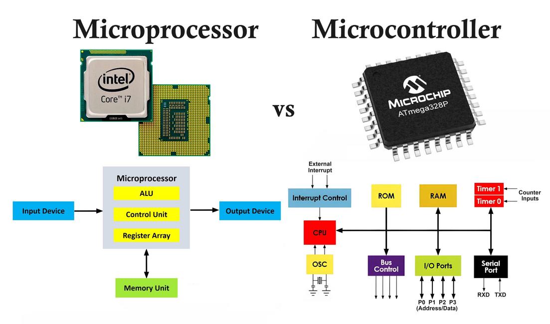
Let’s understand in detail what are the difference between Microprocessor and Microcontroller. Microprocessors and microcontrollers are both essential components in the field of electronics and… Read More »Difference Between Microprocessor and Microcontroller

This article describes a sensor-less BLDC motor driver circuit using 555 timer and DRV10866 motor driver IC, suitable for driving small 5V BLDC fans without… Read More »Brushless DC – BLDC Motor Driver Circuit using 555 Timer IC
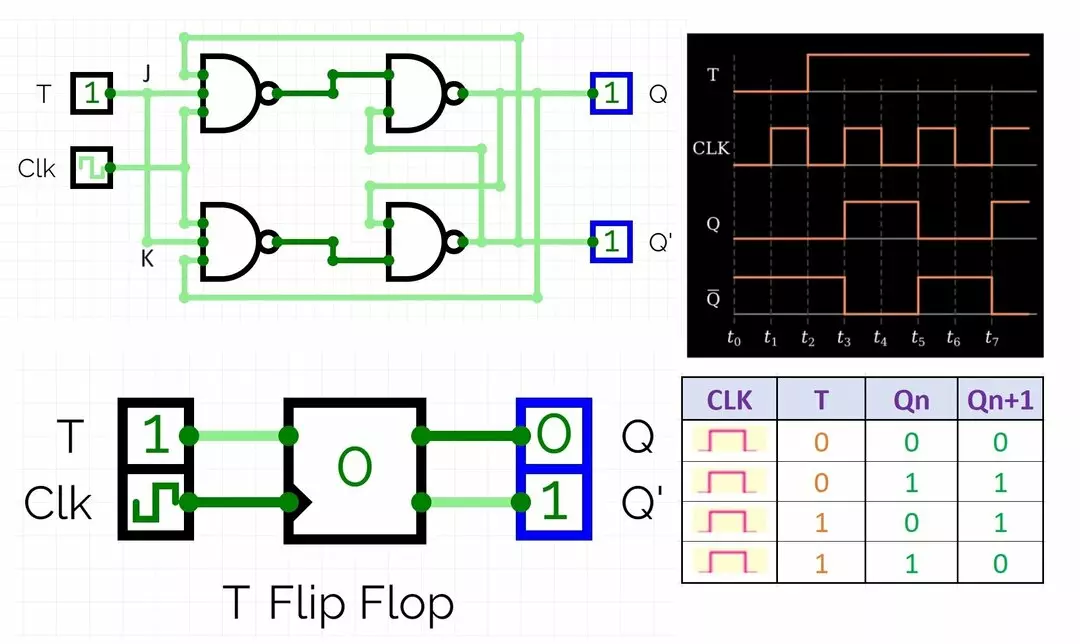
Let’s explore T flip flop truth table and working of its circuit with applications. A T flip-flop, also known as a toggle flip-flop, is a… Read More »T Flip Flop Truth Table, Circuit Diagram, Working and Applications

In this article you will learn how to make an LED chaser circuit using 555 timer IC and CD4017 counter IC. An LED chaser circuit… Read More »LED Chaser Circuit using 555 Timer and CD4017 IC
Let’s see block diagram of microcontroller in detail. microcontroller is a compact electronic device that integrates a central processing unit (CPU), memory (both RAM and… Read More »Microcontroller Block Diagram, Working, Types and Applications