555 Timer Calculator
555 Timer: Astable & Monostable Modes
The 555 timer IC is one of the most versatile and widely used integrated circuits in electronics. Whether you’re designing oscillators, pulse generators, or timers, the 555 timer offers an easy-to-use solution. In this article, we'll dive into the two primary operating modes of the 555 timer—Astable and Monostable—and explore the essential formulas used for calculating various parameters in each mode.
The 555 timer is an analog IC that can be configured in three different modes: Astable, Monostable, and Bistable. Each mode serves a specific purpose:
- Astable Mode: The 555 timer generates a continuous square wave signal, making it ideal for oscillators and pulse generation.
- Monostable Mode: The timer produces a single pulse of a specified duration in response to an external trigger, which is useful for time delay applications.
- Bistable Mode: The IC operates as a flip-flop, providing two stable states and requiring external triggering to change states.
This article focuses on the first two modes: Astable and Monostable.
Astable Mode: Continuous Waveform Generation
In Astable mode, the 555 timer continuously switches between high and low states, creating a square wave output. This mode is often used in clock pulses, tone generation, and LED flashers.
Key Parameters and Formulas
- Frequency (F): The frequency of the oscillation is the number of cycles per second.
It
is given by:
F =
1.44 / ((R1 + 2R2) × C1)-
R1andR2are the resistors connected to the 555 timer.-
C1is the capacitor connected to the timer. - Time Period (T): The time period is the duration of one complete cycle of the
waveform:
T =
1 / F- This represents the time taken for one complete high and low cycle.
- Duty Cycle (%): The duty cycle indicates the percentage of time the output is high
during each cycle. It is calculated as:
Duty Cycle =
(T_high / T) × 100-
T_highis the time the output is high.-
Tis the total time period. - Time High (Th): The time the output remains high is:
T_high =
0.693 × (R1 + R2) × C1 - Time Low (Tl): The time the output remains low is:
T_low =
0.693 × R2 × C1
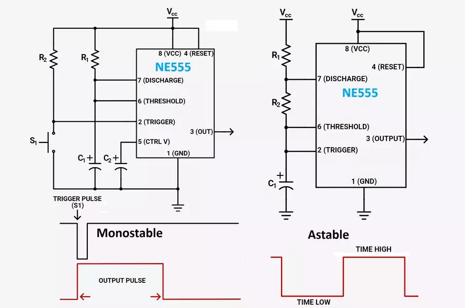
Monostable Mode: Single Pulse Generation
In Monostable mode, the 555 timer generates a single pulse of a specified duration in response to an external trigger. This mode is commonly used for time delays and pulse stretching.
Key Parameter and Formula
- Output Pulse Duration (T_pulse): The length of the pulse generated by the timer is:
T_pulse =
1.1 × R × C-
Ris the resistor connected to the timer.-
Cis the capacitor connected to the timer.
Example Calculations
Example 1: Astable Mode
Suppose we want to design a 555 timer circuit to generate a square wave with a frequency of 1 kHz. We
choose R1 = 10 kΩ, R2 = 20 kΩ, and C1 = 100 nF.
- Calculate Frequency (F):
F =
1.44 / ((10 kΩ + 2 × 20 kΩ) × 100 nF)F ≈ 0.24 kHz
- Calculate Time Period (T):
T =
1 / FT ≈ 4.2 ms
- Calculate Duty Cycle (%):
T_high =
0.693 × (10 kΩ + 20 kΩ) × 100 nFT_high ≈ 2.08 ms
Duty Cycle =(2.08 ms / 4.2 ms) × 100Duty Cycle ≈ 49.52%
Example 2: Monostable Mode
Suppose we want a pulse duration of 5 milliseconds. We choose R = 47 kΩ and need to find
the
required capacitor value.
- Calculate Capacitor Value (C):
C =
T_pulse / (1.1 × R)C ≈ 0.094 µF
Conclusion
The 555 timer IC is a powerful tool for generating precise time delays and waveforms. Understanding its operation in Astable and Monostable modes allows you to harness its capabilities for a wide range of applications. By mastering the formulas provided, you can design circuits with specific timing characteristics and achieve accurate results in your electronic projects.
Feel free to experiment with different resistor and capacitor values to see how they affect the output of the 555 timer. With practice, you’ll gain a deeper understanding of how this versatile IC can be used effectively in various applications.