The diac is basically a two-terminal device. Here we will discuss the Symbol of Diac and it’s VI characteristics. It is such a combination of semiconductor layers that allows triggering in both directions. The diac is used as a triggering device for the TRIAC circuits. Here we will discuss the Symbol of Diac and it’s VI characteristics.

Symbol and structure of Diac:
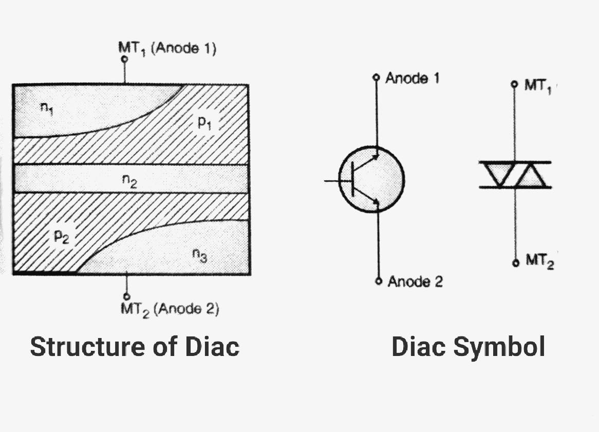
The arrangement of a semiconductor layer is as shown in Figure. The two terminals accessible to the user are MT1 and MT2.
When MT1 is positive with respect to MT2 the conduction takes place through the structure formed by the layers p1-n2-p1-n1 which is equivalent to an SCR.

Similarly, when MT2 is positive with respect to MT1 the conduction takes place through the structure formed by the layers which is another SCR. Therefore, the equivalent circuit of Diac which is SCRs connected back to back.
The figure shows the circuit symbols for the diac. The arrows indicate that the diac can conduct in both directions. The other symbol of diac is identical to that of a Triac without a gate terminal.
VI characteristics of DIAC:
The static characteristic of diac is as shown in graph We may think of Diac being equivalent to a bipolar transistor with no base connection.
Diac can be turned on by either a positive or negative half cycle of an ac voltage. For the positive cycle of ac voltage, if the applied voltage is less than the forward breakover voltage a very small current called the “leakage current'”, flows through the device.
This current is produced due to the drifting of electrons and the holes at the depletion region and is not sufficient to cause conduction.
Hence the diac remains in the non-conducting mode called the “blocking state” or off state.
As soon as the applied voltage reaches the breakover voltage, (Vbo) the device starts conducting. The current through the device starts increasing and the voltage across it starts decreasing.
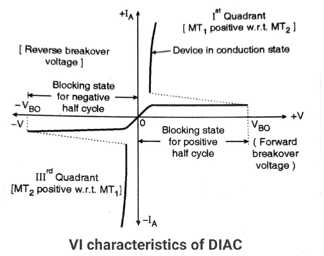
This region is the “conduction state”. There is no control over the breakover voltage for the diac remains unchanged as the gate terminal is absent here. The characteristics of the diac are very much similar to that of a Triac.
For the positive half cycle of the ac supply, the characteristic is obtained in the first quadrant and a similar characteristic for the negative half cycle is obtained in the third quadrant as shown in Figure.
The breakover voltage of a diac ranges between 28 Volts to 42 Volts. The typical turn-on time ranges from 50 to 500 nsec.
The turn off time is much longer, about 100 nsec. Diacs have a power handling capacity between 300 mW to 1W which shows that it is a low power device.
DIAC Applications:
DIAC is basically used as a triggering device for Triac. The following control systems use DIAC for this purpose.
- Lamp dimmer
- Fan speed regulator
- Temperature controller
Disadvantages of DIAC:
- It is a low power device.
- It does not have a control terminal.